Vehicle driver wheelchair lift

Inactive Publication Date: 2011-01-06
DARNELL SCOTT ALAN +1
View PDF9 Cites 15 Cited by
  • Summary
  • Abstract
  • Description
  • Claims
  • Application Information

AI Technical Summary

Benefits of technology

[0008]Therefore, there is a need to provide further options for wheelchair confined people such as a better wheelchair lifting device that reduces at least some of the above problems.
[0009]In a first exemplary embodiment, a bearing is fixed to the vehicle and a pivot arm has a first end rotationally captured within the bearing and free to rotate therein. The pivot arm also has an outer end configured with a fork and a parallelogram linkage to allow vertical movement of the fork while maintaining the fork in a horizontal orientation. The fork on a wheelchair first exemplary embodiment also has a first linear actuator to horizontally rotate the pivot arm to move the wheelchair horizontally in and out of the vehicle, and a second linear actuator to raise and lowe

Problems solved by technology

Persons confined to wheelchairs have limited options pertaining to driving vehicles.
Aside from the obvious drawback of having to transfer between chairs, which is time consuming, the driver must also be able to readily store his wheelchair somewhere in the vehicle and must do this after having transferred into the dedicated chair.
Normally this means a passenger is required to handle the wheelchair, and that obviously limits the freedom of the driver to drive when and where he wants.
But such wheelcha

Method used


Image

  • Vehicle driver wheelchair lift
  • Vehicle driver wheelchair lift
  • Vehicle driver wheelchair lift

Examples


Embodiment Construction

Exemplary Best Mode (Preferred Exemplary Embodiment)

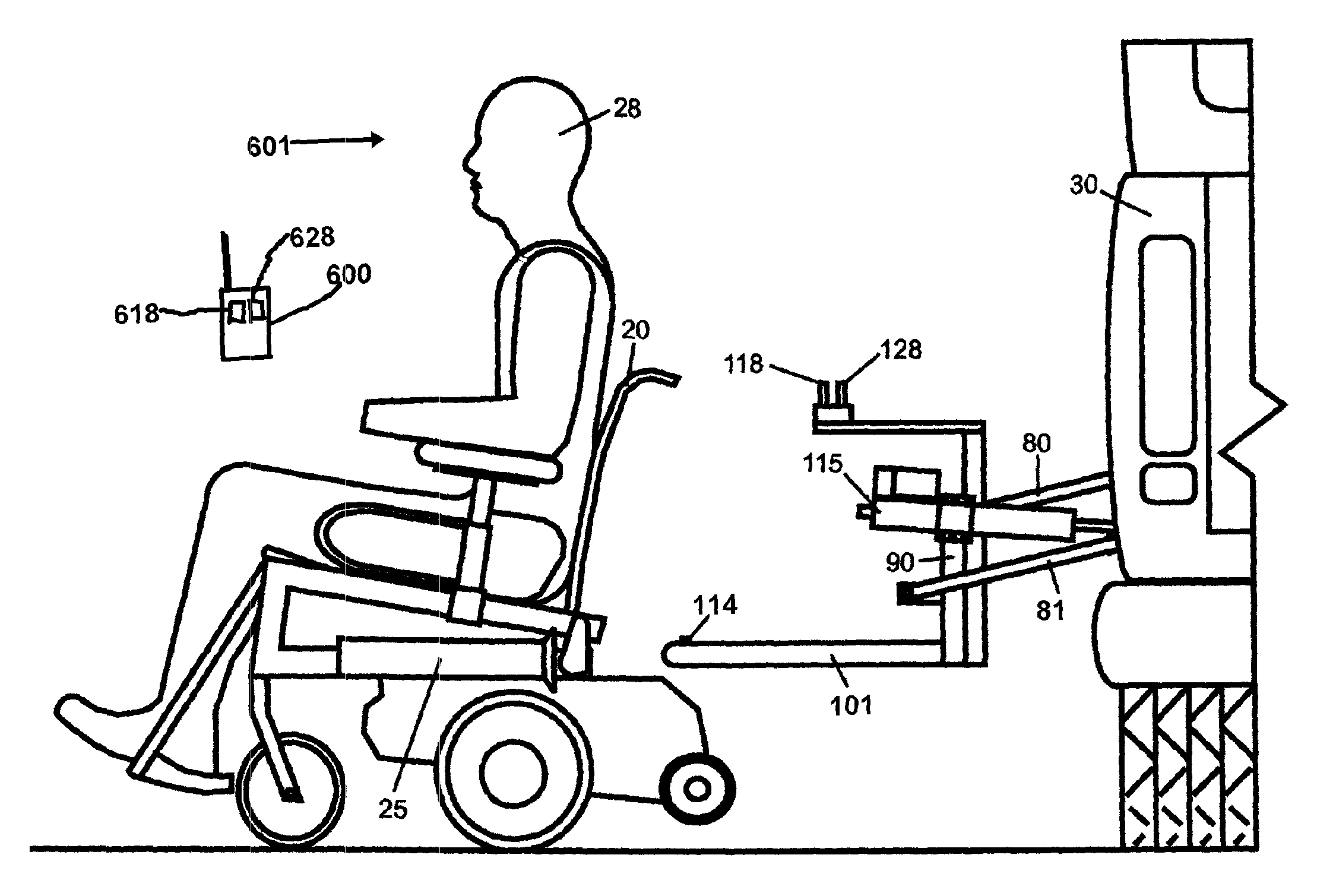
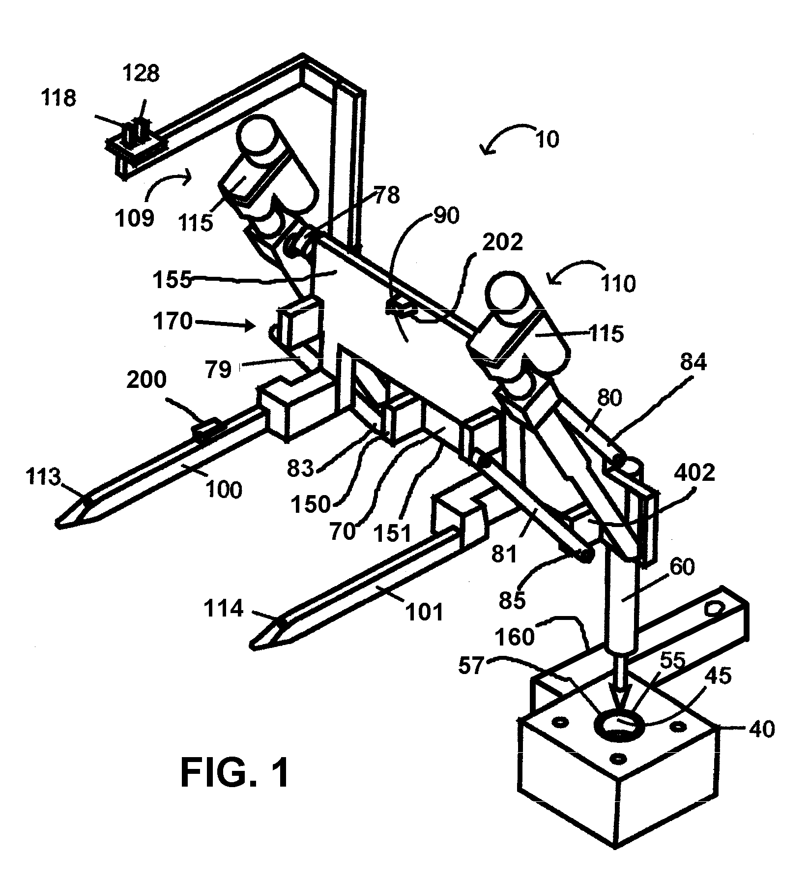
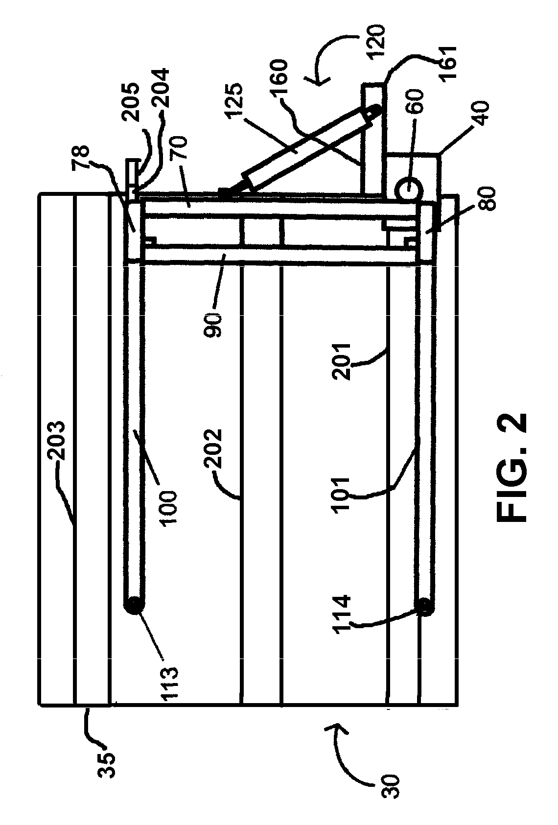
[0018]The seven FIGS. 1-7 illustrate a first exemplary embodiment of a system 10 for lifting an driver 28 in a wheelchair 20 into and out of a vehicle 30. FIG. 1 shows system 10 without wheelchair 20 or vehicle 30, while FIG. 5 shows wheelchair 20 in place and system 10 in a first inside position 130 where driver 28 is properly located and oriented to drive vehicle 30. Vehicle 30 is a Dodge, Chevy, or Ford “Quad-Cab” truck, but could be any other vehicle having a sufficiently large side opening. FIG. 3 shows vehicle 30 has a sturdy frame 35 typically including a bar 201, a bar 202 and a bar 203 and other bars (not shown). Vehicle 30 has so-called “suicide-swing” rear door 502 that have a rear hinge (not shown) to open from the front and thus away from a forward door 506, providing a wider opening 510 for wheelchair 20 to enter vehicle 30. For safety purposes, a sensor 200 and a sensor 202 are provided to sense when wheelchair 20 is...


PUM


Abstract

Disclosed is a vehicle driver wheelchair lift, the lift having a bearing mount fixed to the vehicle that rotationally captures a pivot rod to which a pair of forks are attached by a parallelogram linkage. The rod rotates in the bearing to move the forks horizontally in and out of the vehicle, while the parallelogram linkage expands and contracts to raise and lower the forks. The purpose of the parallel linkage is to allow the forks to move vertically while maintaining a horizontal position. The forks are adapted to engage a pair of horizontal fork receivers fixed to a wheelchair. A vertical linear actuator expands and contracts the linkage to raise and lower the forks vertically. A motor turns the pivot rod to rotate the forks horizontally. In one exemplary embodiment, a lock on the forks secures the receivers and chair on the forks and a sensor signals when the receivers are in locked position suitable for raising and lowering. In one exemplary embodiment, the parallel linkage has outwardly offset lower joints to establish a preset raised position at maximum extension.

Description

CROSS-REFERENCE TO RELATED APPLICATIONS[0001]This application is a continuation-in-part of and claims the benefit of U.S. patent application 11 / 849,283, filed on Sep. 1, 2007 and U.S. Provisional Patent Application 60 / 841,637, filed on Sep. 1, 2006.FEDERALLY SPONSORED RESEARCH[0002]Not Applicable.BACKGROUND OF THE INVENTION[0003]This invention relates to the field of self-loading or unloading vehicles and more specifically to loading and unloading wheelchairs from vehicles such as classified in class 414, subclass 540.[0004]Persons confined to wheelchairs have limited options pertaining to driving vehicles. Typically, vehicles that are available to disabled persons are necessarily large vehicles, such as vans, which provide internal room sufficient to contain prior art wheelchair lift or ramp devices. Ramp-type devices require the most room inside a vehicle, since a pathway from the ramp—typically on the side of the vehicle—to the driver's seat area of the vehicle must be kept clear...

Claims


Application Information

Patent Timeline
IPC IPC(8): A61G3/06A61G3/02
CPCA61G3/0808A61G7/1017A61G3/062
Inventor DARNELL, SCOTT ALANGOTTER, DAVID WAYNE
Owner DARNELL SCOTT ALAN
Why Eureka
Try Eureka