
Surface texture measurement apparatus and roundness measuring apparatus

a measurement apparatus and surface texture technology, applied in the direction of measurement devices, mechanical roughness/irregularity measurements, instruments, etc., can solve the problems of disadvantageous structure in terms of cost, adverse effects of measurement target surfaces on measurement results, etc., and achieve the effect of avoiding an increase in the size of the detector

Active Publication Date: 2011-01-13
MITUTOYO CORP
View PDF0 Cites 20 Cited by
  • Summary
  • Abstract
  • Description
  • Claims
  • Application Information

AI Technical Summary

Benefits of technology

[0007]An advantage of some aspects of the invention is to provide a surface texture measurement apparatus that is equipped with a small inexpensive detector and that makes it possible to carry out uninterrupted measurement by changing the measuring force of the detector without any need to suspend a measurement program. In addition, a roundness measuring apparatus is provided.
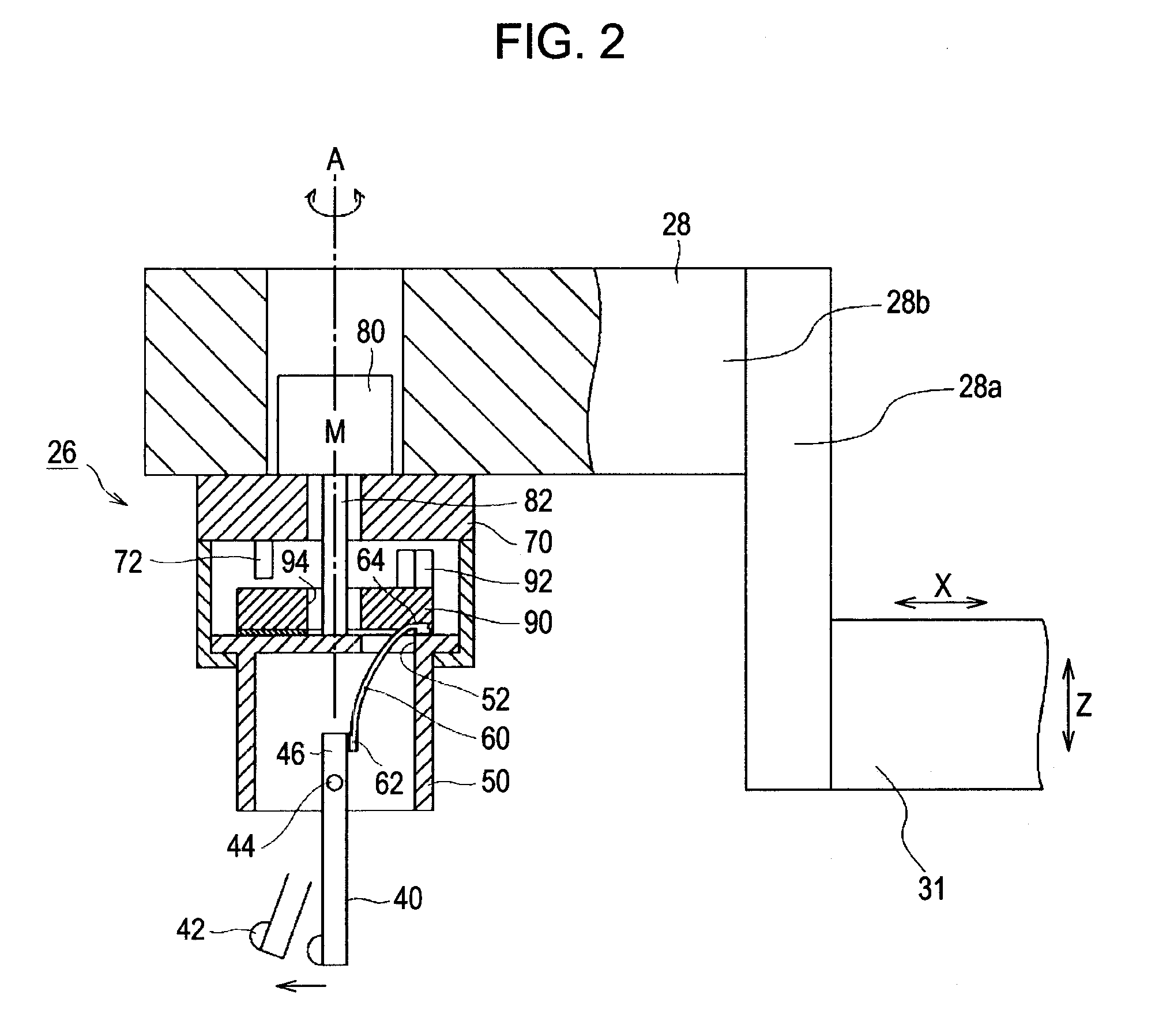
[0012]In the above surface texture measurement apparatus having the preferred configuration, it is further preferable that the second rotation range should be divided into a normal-direction-side rotation range that continues from the first rotation range in the direction of normal rotation and a reverse-direction-side rotation range that continues from the first rotation range in the direction of reverse rotation; the rotary motor should cause the holding member alone to rotate in the normal direction in a state in which rotation of the elastic force adjustment member in the direction of normal rotation is restricted so as to increase the amount of elastic deformation in the normal-direction-side rotation range; and the rotary motor should cause the holding member alone to rotate in the reverse direction in a state in which rotation of the elastic force adjustment member in the direction of reverse rotation is restricted so as to decrease the amount of elastic deformation in the reverse-direction-side rotation range.
[0015]The range of the rotational position of the holding member driven by the rotary motor is divided into the first rotation range in which the displacement direction of the contact part is turned and the second rotation range in which the elastic force of the elastic member is adjusted. Therefore, it is possible to change a pressing force acting against the measurement target surface in a state in which the contact part is in contact with the measurement target object, that is, a measuring force, by means of the rotary motor. Since it is not necessary to suspend a measurement program for the purpose of changing the measuring force, it is possible to carry out continuous measurement without any interruption. In addition, a conventional rotary motor of a detector (the stylus, the holding member, and the elastic member) is used also as a mechanism for adjusting a measuring force. Therefore, it is not necessary to provide a driver, a controlling scale, and the like for changing a measuring force automatically as additional components inside the detector. Therefore, it is possible to avoid an increase in the size of the detector. In addition, such a structure is advantageous in terms of cost. As explained above, a surface texture measurement apparatus and a roundness measuring apparatus according to aspects of the invention make it possible to carry out uninterrupted measurement by changing the measuring force of a detector without any need to suspend a measurement program. In addition, it is possible to use a small inexpensive detector.

Problems solved by technology

Especially when a measurement target surface is soft, an excessive pressing force of a stylus that is applied onto the measurement target surface will have adverse effects on the result of measurement.
In addition, such a structure is disadvantageous in terms of cost.

Method used


Image

  • Surface texture measurement apparatus and roundness measuring apparatus
  • Surface texture measurement apparatus and roundness measuring apparatus
  • Surface texture measurement apparatus and roundness measuring apparatus

Examples


Embodiment Construction

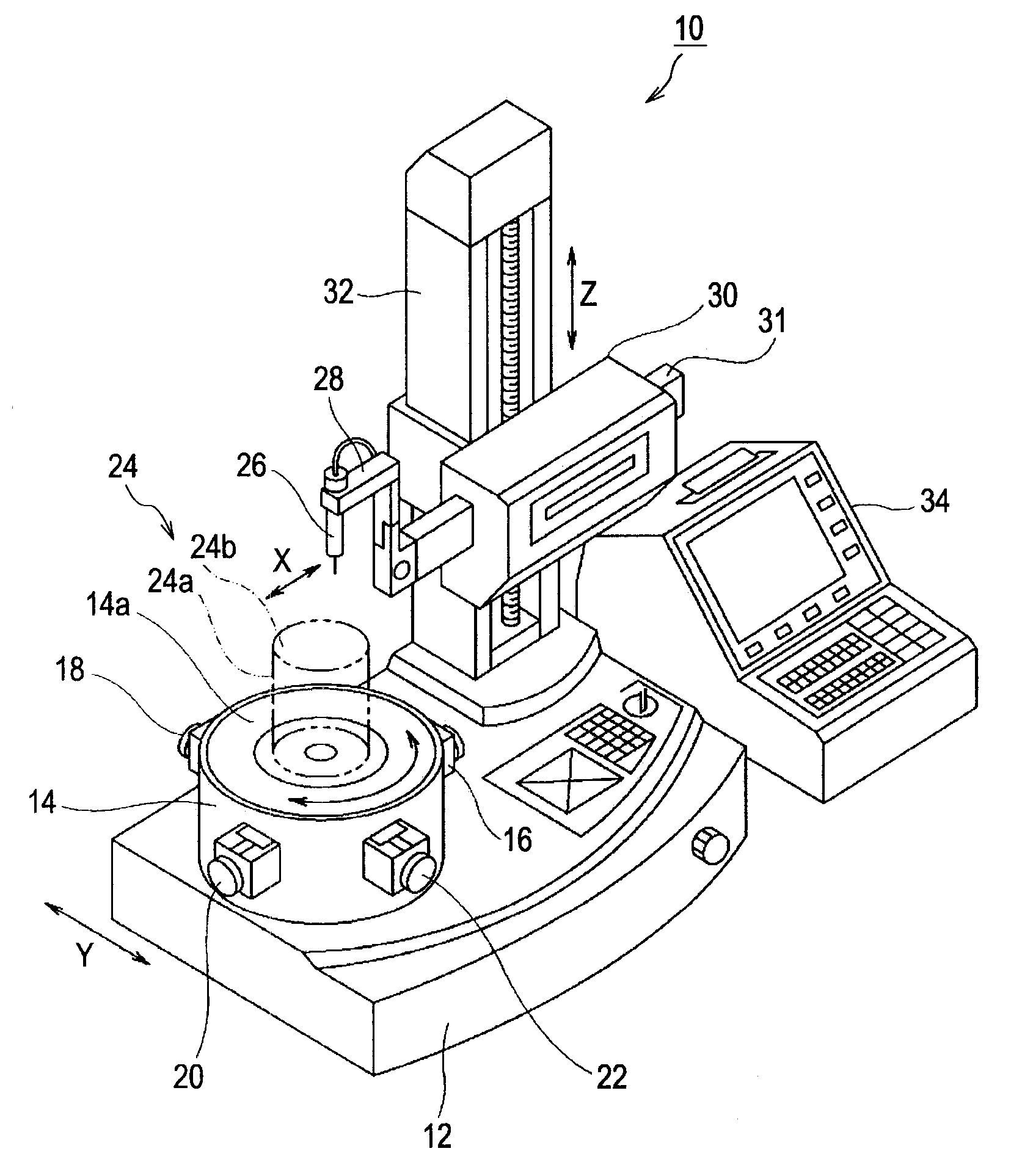
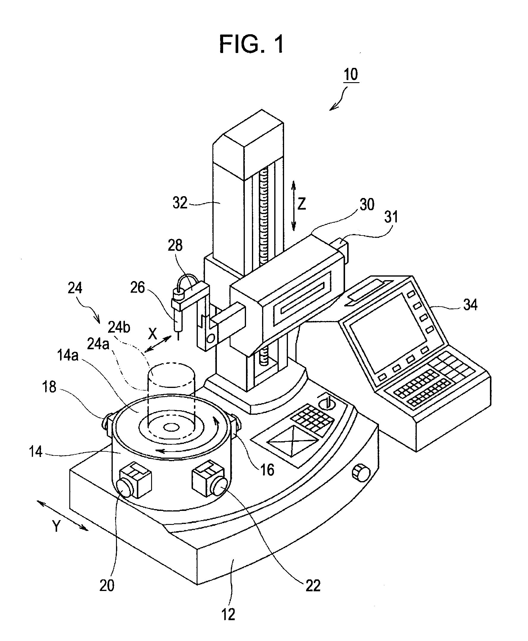
[0022]With reference to the accompanying drawings, a preferred embodiment of the present invention will now be explained in detail. FIG. 1 is a diagram that schematically illustrates an example of the appearance of a roundness measuring apparatus 10 according to an exemplary embodiment of the invention. The illustrated roundness measuring apparatus 10 includes a base 12, a turntable 14 that is provided on the base 12 as a rotatable table, an X position adjusting means 16 for adjusting the X-direction position of the turntable 14, a Y position adjusting means 18 for adjusting the Y-direction position of the turntable 14, an X inclination adjusting means 20 for adjusting the X-direction inclination of a surface (14a) of the turntable 14 on which a measurement target object 24 is placed, a Y inclination adjusting means 22 for adjusting the Y-direction inclination of the object placement surface 14a of the turntable 14, a detector 26 that can be brought into contact with a surface of th...


PUM


Abstract

A roundness measuring apparatus includes: a stylus having a contact part; a holding member that holds the stylus while allowing displacement of the contact part; an elastic member that presses the contact part against a measurement target object; a detector holder that supports the holding member rotatably; a motor; an elastic force adjustment member that is rotatable and concentric with the holding member; a joining section that joins the elastic force adjustment member with the holding member to maintain relative rotational positions; and a restricting section that restricts rotation of the elastic force adjustment member at a predetermined rotational position. The displacement direction of the contact part is adjusted in a first rotation range. The rotational position of the holding member relative to the rotational position of the elastic force adjustment member changes with the rotation of the elastic force adjustment member being restricted in a second rotation range.

Description

BACKGROUND OF THE INVENTION[0001]1. Field of the Invention[0002]The present invention relates to a surface texture measurement apparatus that measures the texture of a measurement target surface on the basis of the displacement of the contact part of a stylus. The displacement is detected in a state in which the contact part of the stylus is in contact with the measurement target surface. In addition, the invention relates to a roundness measuring apparatus.[0003]2. Description of the Related Art[0004]A roundness measuring apparatus that is used for acquiring various kinds of data related to the roundness of a measurement target object such as a cylindrical column, a circular cylinder, or the like is known well. The roundness data includes, for example, data regarding circularity, concentricity, and coaxiality. A roundness measuring apparatus measures and calculates the roundness of a measurement target object as follows. A measurement target object, which is an object to be measure...

Claims


Application Information

Patent Timeline
Patent Type & Authority Applications(United States)
IPC IPC(8): G01B5/20G01B5/00
CPCG01B3/008G01B5/28G01B5/201G01B5/012
Inventor NAKAYAMA, TATSUKISHINDO, HIDEKI
Owner MITUTOYO CORP
Learn More