Single component intake/exhaust valve member, fuel distribution system, and cooling system for combustion-powered fastener-driving tool

a single-component, combustion-powered technology, applied in the direction of nailing tools, valve arrangements, combustion engines, etc., can solve the problems of not always ideal to dispose of a fan at the upper axial region of the combustion chamber, the operation cycle of such conventional combustion-powered fastener-driving tools is slower than that of conventional pneumatically-powered fastener-driving tools, and the inability to readily incorporate or operatively associate auxiliary cooling structures or devices with the combustion

a single-component, combustion-powered technology, applied in the direction of nailing tools, valve arrangements, combustion engines, etc., can solve the problems of not always ideal to dispose of a fan at the upper axial region of the combustion chamber, the operation cycle of such conventional combustion-powered fastener-driving tools is slower than that of conventional pneumatically-powered fastener-driving tools, and the inability to readily incorporate or operatively associate auxiliary cooling structures or devices with the combustion

US20110005502A1Active Publication Date: 2011-01-13ILLINOIS TOOL WORKS INC

Image

  • Single component intake/exhaust valve member, fuel distribution system, and cooling system for combustion-powered fastener-driving tool
  • Single component intake/exhaust valve member, fuel distribution system, and cooling system for combustion-powered fastener-driving tool
  • Single component intake/exhaust valve member, fuel distribution system, and cooling system for combustion-powered fastener-driving tool

Examples


Embodiment Construction

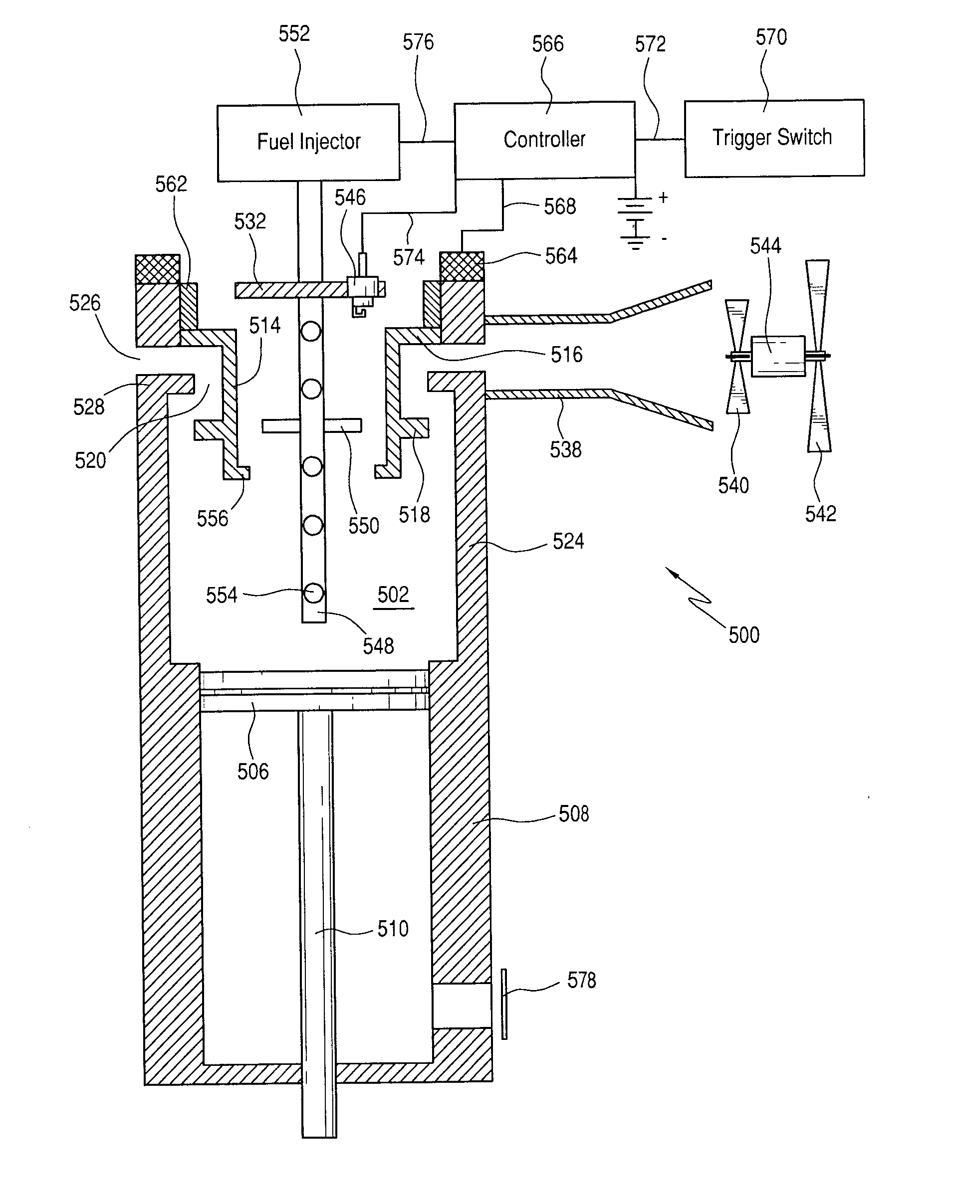
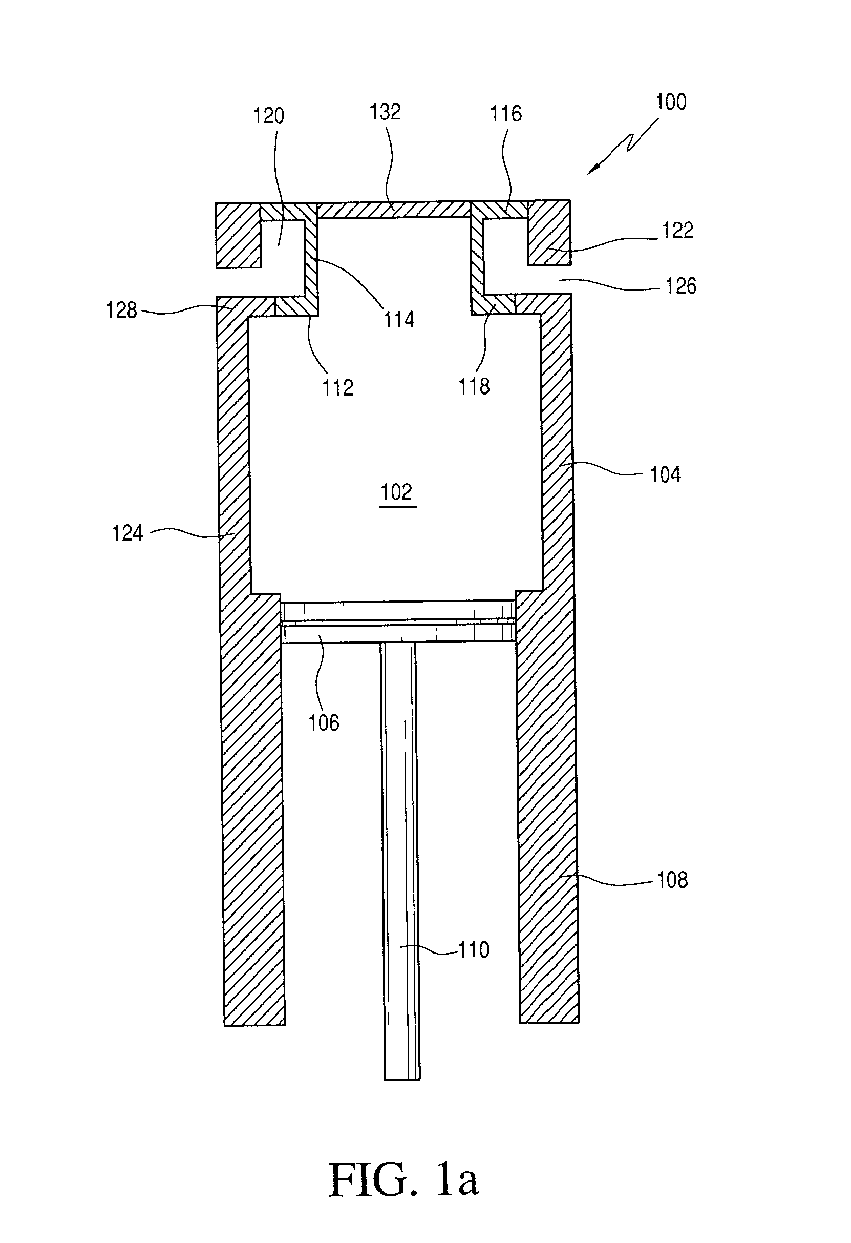
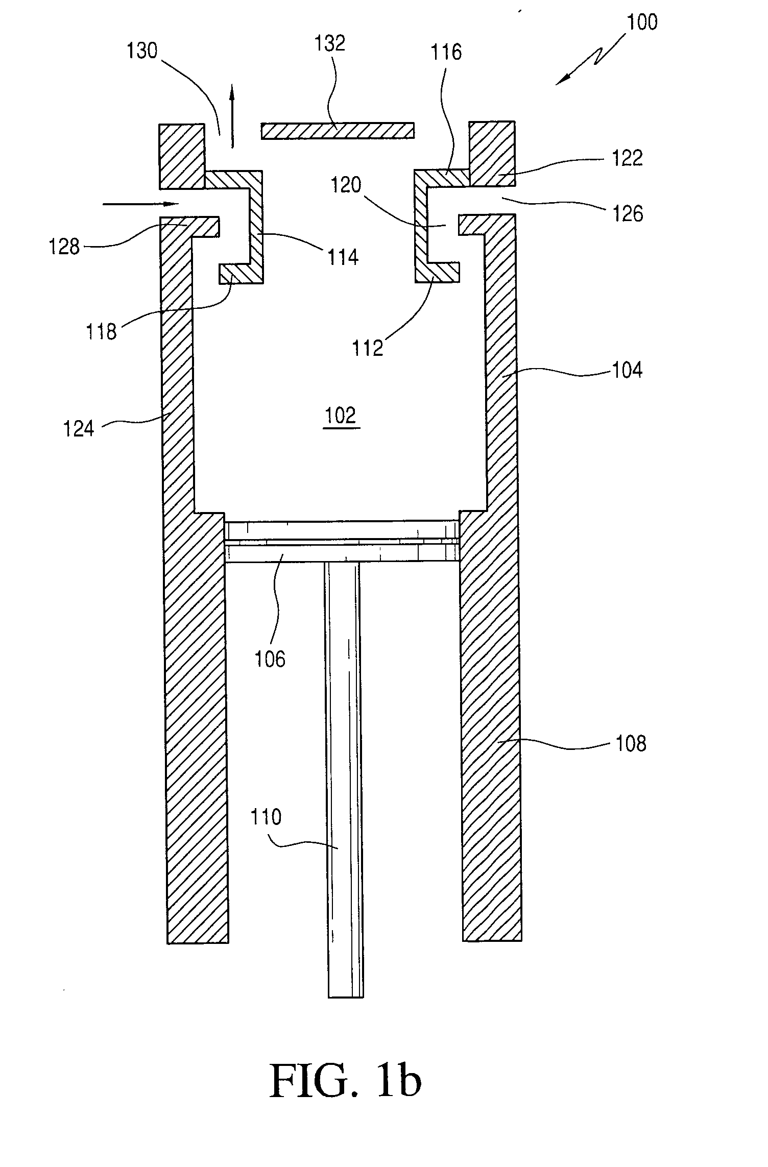
[0016]Referring now to the drawings, and more particularly to FIGS. 1a and 1b thereof, a first embodiment of a new and improved combustion chamber and piston-cylinder system, having a new and improved intake / exhaust valve structure, as constructed in accordance with the principles and teachings of the present invention, incorporated within the combustion chamber and piston-cylinder system, is illustrated and is generally indicated by the reference character 100. More particularly, it is seen that the first embodiment combustion chamber and piston-cylinder system 100 comprises a combustion chamber 102, as defined internally within a substantially cylindrically shaped combustion chamber housing 104, and a working piston 106 movably disposed in a vertically reciprocal manner within a surrounding cylinder 108. The working piston 106 has a driver blade or similar fastener-driving implement 110 fixedly attached to the undersurface portion thereof, and it is seen that the upper surface por...


PUM


Abstract

A new and improved combustion-powered fastener-driving tool utilizes a new and improved single component in-take / exhaust valve member which integrally defines both the intake and exhaust valves thereon. The intake / exhaust valve member is axially movable within the combustion chamber, and operatively cooperates with wall structure of the combustion chamber. When the intake / exhaust valve member is disposed, for example, at a first upper position, both the intake and exhaust ports defined within the wall structure of the combustion chamber are closed so as to permit the ignition and combustion phases of the tool-firing cycle to proceed, whereas, conversely, when the intake / exhaust valve member is disposed, for example, at a second lower position, both the intake and exhaust ports within the combustion chamber are open so as to permit incoming air to scavenge combustion exhaust products and to subsequently mix with injected fuel in preparation for the commencement of another tool-firing cycle.

Description

CROSS-REFERENCE TO RELATED PATENT APPLICATION[0001]This patent application is related to, based upon, and effectively a utility patent application conversion from U.S. Provisional Patent Application Ser. No. 61 / 006,305, which was filed on Jan. 4, 2008, the filing date benefits of which are hereby claimed.FIELD OF THE INVENTION[0002]The present invention relates generally to combustion-powered fastener-driving tools, and more particularly to a new and improved single component intake / exhaust valve member, a fuel injection and distribution system, and a supplemental or auxiliary air flow system for a combustion-powered fastener-driving tool wherein the single component valve member is structured or configured for structurally cooperating with wall structure of the tool combustion chamber so as to effectively define both the intake and exhaust valve structure for the combustion-powered fastener-driving tool, wherein fuel injection manifold and accelerator plate structure is incorporate...

Claims


Application Information

Patent Timeline
13 Jan 2011
Publication
US20110005502A1
IPC
F02B33/00; F01L3/00
CPC
B25C1/08
Inventors
ADAMS, JOSEPH S.