Pneumatic tire

a technology of pneumatic tires and cylinders, applied in the field of pneumatic tires, can solve the problems of insufficient traction, side slippage, and deterioration of the cylinder axis, and achieve the effect of improving wear resistance and partial wear resistan

Active Publication Date: 2011-01-13
BRIDGESTONE CORP
View PDF14 Cites 19 Cited by
  • Summary
  • Abstract
  • Description
  • Claims
  • Application Information

AI Technical Summary

Benefits of technology

[0026]According to the present invention, it is possible to provide a pneumatic tire having improved wear resistance and partial wear resistance while sufficiently securing heat radiation, by optimizing a tread pattern.

Problems solved by technology

However, when the width of the rib-shaped land portion arranged in the central region is too great, the fraction for climbing a hill deteriorates, and a side slippage likely occurs at the time of steering because of absence of the groove extending in the circumferential direction in the central region.
Also, sufficient traction cannot be obtained because of absence of a transverse groove in the central region.
However, because the groove traversing the central land portion is a narrow groove, the central land portion deforms in the tire circumferential direction due to a friction force between the central land portion and a road surface at the time when the tire rotates under load, and the transverse narrow groove closes in a road contacting region thereof, which causes the adjacent central land portions to be substantially connected with each other.

Method used


Image

  • Pneumatic tire
  • Pneumatic tire
  • Pneumatic tire

Examples


example 1

[0084]Next, as a tire for heavy load with size 16.00R25, there were prepared a tire (Conventional Example tire) having conventional lug grooves; a comparative example tire (Comparative Example tire) provided with a central land portion and having, at the central land portion, inclined narrow grooves configured differently from the inclined narrow grooves according to the present invention; and a tire (Example tire 1) provided with a central land portion and having, at the central land portion, inclined narrow grooves according to the present invention, and performance evaluation was made to those prepared tires, which will be described below.

[0085]As shown in FIG. 5, Conventional Example tire has, at a tread portion, lug grooves extending from respective tread ends on a tire central equator plane side and terminating without reaching the tire central equator plane, and 36 lug grooves are provided on the circumference, the characteristics of which tire are shown in Table 1. As shown ...

example 2

[0090]Next, tires (Example tires 2-5) having the inclined narrow groove according to the present invention are prepared as a tire for heavy load with a tire size 16.00R25, and performance evaluations are made on the prepared tires, which will be described below.

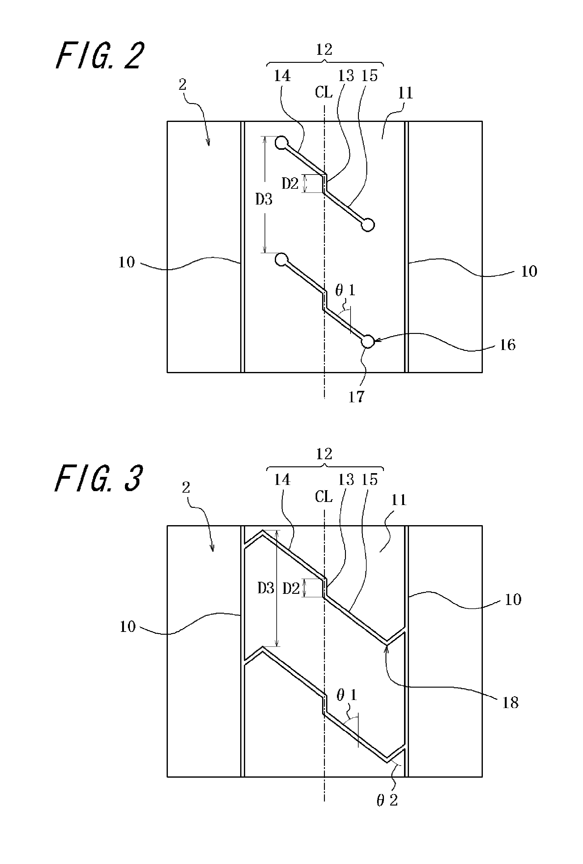
[0091]Example tire 2 and Example tires 3-5 are provided with inclined narrow grooves, as shown in FIG. 2 and FIG. 4A, respectively, each constituted of a first small groove provided in a central land portion defined by circumferential narrow grooves and extending along a tire circumferential direction, a second small groove extending from one end portion of the first small groove toward one of the circumferential narrow grooves so as to incline with respect to the tire circumferential direction at 45°, and a third small groove extending from the other end portion of the first small groove to the other one of the circumferential narrow grooves so as to incline with respect to the tire circumferential direction at 45-46°. Furth...


PUM


Abstract

A pneumatic tire has a tread pattern designed to provide improved heat dissipation properties, wear resistance, and uneven wear resistance. The tire has arranged in a tread (2) two circumferential fine grooves (10) disposed on opposite sides of the equatorial surface (CL) of the tire and extending in the circumferential direction of the tire, and the circumferential fine grooves (10) define a center land section (11). In the center land section (11) are formed oblique fine grooves (12) each having a first small groove (13) extending in the tire's circumferential direction, a second small groove (14) extending obliquely relative to the circumferential direction from one end of the first small groove (13) toward one circumferential fine groove, and a third small groove (15) extending obliquely relative to the circumferential direction from the other end of the first small groove (13) toward the other circumferential fine groove.

Description

TECHNICAL FIELD[0001]The present invention relates to a pneumatic tire having, on a tread portion, two circumferential narrow grooves extending in a tire circumferential direction and arranged on both sides of a tire equator plane, and a central land portion defined by the circumferential narrow grooves, and, in particular, to a pneumatic tire for heavy load, and secures sufficient heat radiation of the pneumatic tire while improving wear resistance and partial wear resistance of the pneumatic tire.BACKGROUND ART[0002]For a pneumatic tire for heavy load for use in a construction vehicle, a significantly high load-bearing ability and a traction performance are required as compared with a pneumatic tire for heavy load such as a tire for use in a truck, bus or light-weight truck. For this reason, conventionally, a so-called rib-lug pattern has been generally employed for a tire tread pattern in which a rib-shaped land portion continuously extending in a tire circumferential direction i...

Claims


Application Information

Patent Timeline
Patent Type & Authority Applications(United States)
IPC IPC(8): B60C11/00
CPCB60C11/0309B60C11/0311B60C11/042B60C2200/065B60C2200/06B60C2011/0381B60C11/13B60C11/032B60C11/04
Inventor ONO, HIROAKIFUKUSHIMA, MASAHARU
Owner BRIDGESTONE CORP
Why Eureka
Try Eureka