
Air spring down-pressure system for implement

a technology of air springs and implements, which is applied in the field of suspension systems, can solve the problems of increasing requiring greater down pressure for constant-depth furrows, and reducing so as to increase the relative down pressure of the suspension system, increase and reduce the mechanical advantage of the arm

Active Publication Date: 2011-01-13
LANDOLL
View PDF13 Cites 9 Cited by
  • Summary
  • Abstract
  • Description
  • Claims
  • Application Information

AI Technical Summary

Benefits of technology

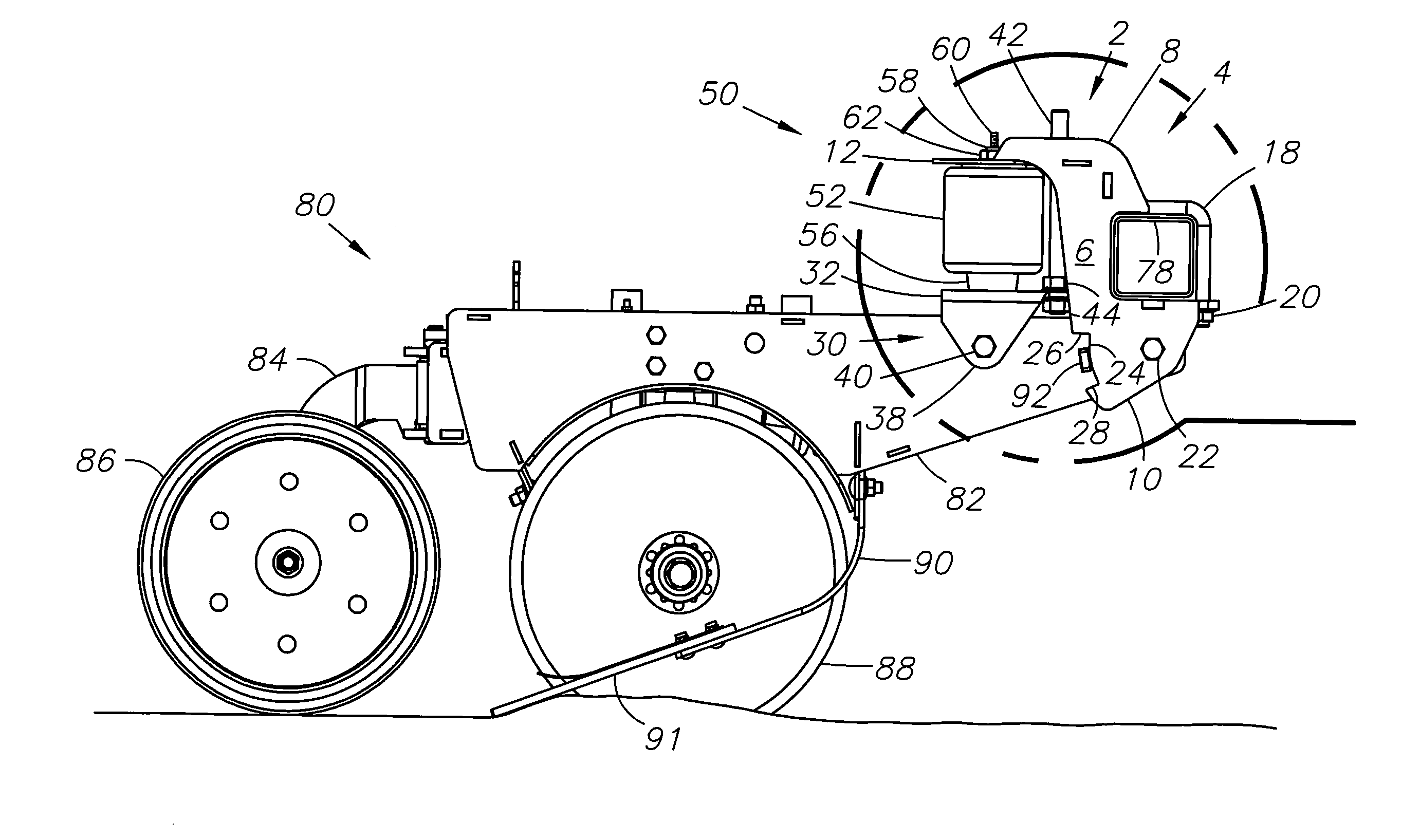
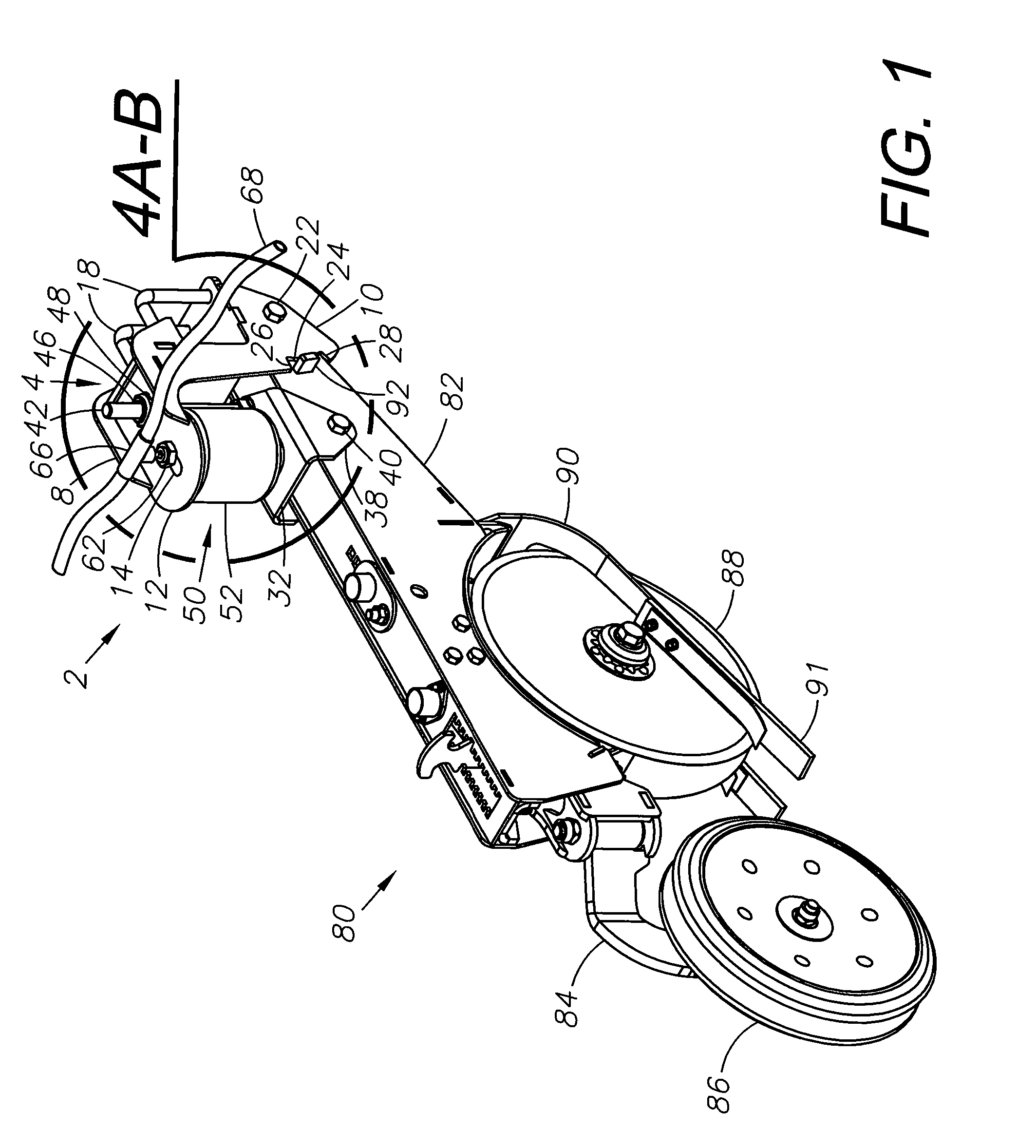
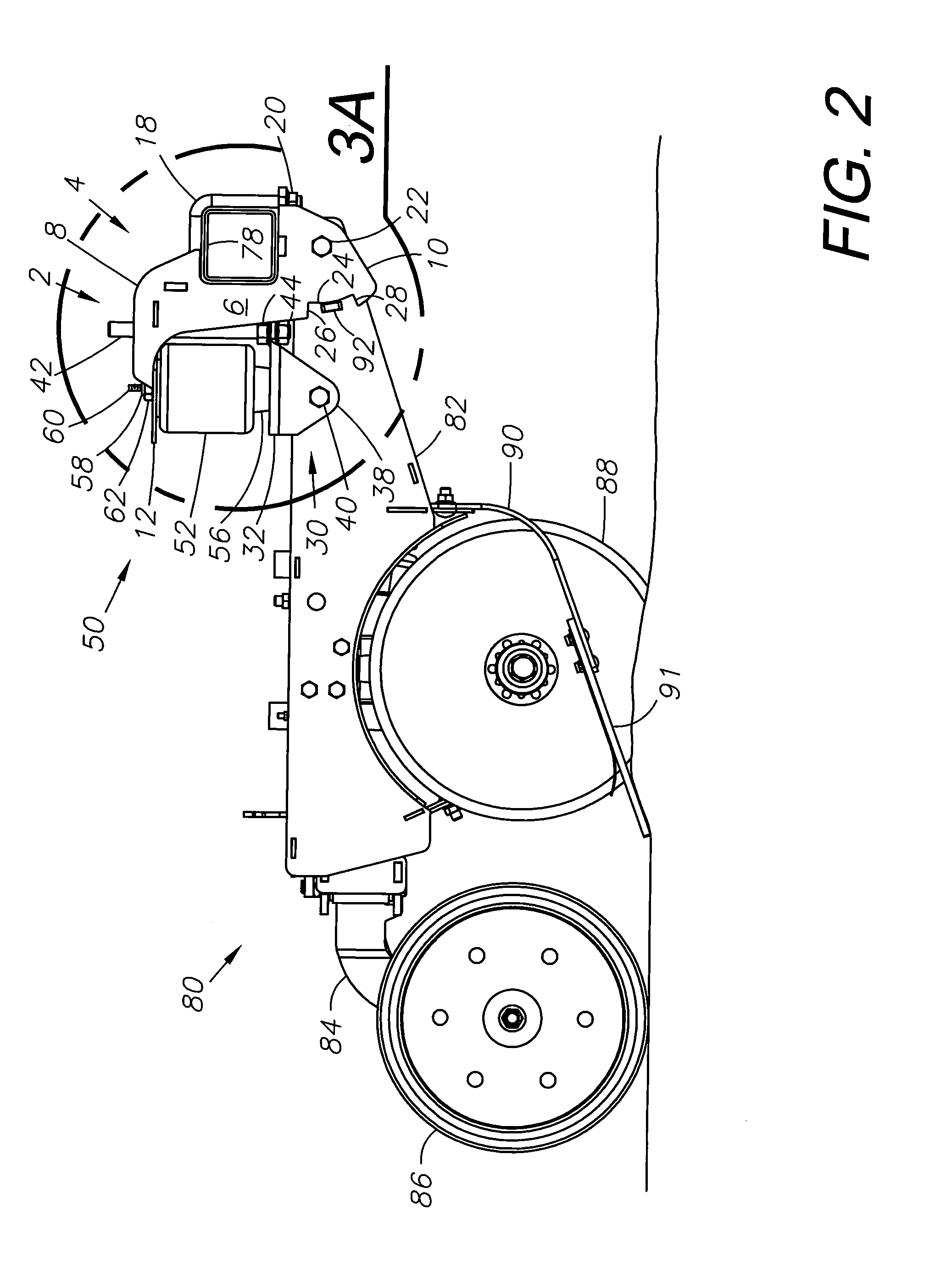
[0010]The amount of down pressure exerted by the suspension system upon the arm can be adjusted by varying the air pressure within the air spring, by moving the air spring assembly forward or backward within the apertures, or both. The air springs are connected to a source of air pressure such as an air compressor. Moving the air spring assembly in a rearward position within the apertures creates a longer distance between the pivot point at the end of the arm and the pivot point of the bottom plate, thereby decreasing the mechanical advantage of the arm and increasing the relative down pressure of the suspension system. Conversely, moving the air spring assembly forward in the apertures increases the mechanical advantage of the arm and decreases the relative down pressure of the suspension system upon the arm. For example, field conditions may necessitate greater down pressure in opener assemblies to accommodate hard ground conditions, field debris and similar conditions associated with greater opener resistance. Moreover, selective opener assemblies, such as those following the tractor wheels and encountering compacted soil conditions, may require greater down pressure for constant-depth furrows.

Problems solved by technology

Moving the air spring assembly in a rearward position within the apertures creates a longer distance between the pivot point at the end of the arm and the pivot point of the bottom plate, thereby decreasing the mechanical advantage of the arm and increasing the relative down pressure of the suspension system.
Moreover, selective opener assemblies, such as those following the tractor wheels and encountering compacted soil conditions, may require greater down pressure for constant-depth furrows.

Method used


Image

  • Air spring down-pressure system for implement
  • Air spring down-pressure system for implement
  • Air spring down-pressure system for implement

Examples


Embodiment Construction

I. Introduction and Environment

[0020]As required, detailed aspects of the disclosed subject matter are disclosed herein; however, it is to be understood that the disclosed aspects are merely exemplary of the invention, which may be embodied in various forms. Therefore, specific structural and functional details disclosed herein are not to be interpreted as limiting, but merely as a basis for the claims and as a representative basis for teaching one skilled in the art how to variously employ the present invention in virtually any appropriately detailed structure.

[0021]Certain terminology will be used in the following description for convenience in reference only and will not be limiting. For example, up, down, front, back, right and left refer to the invention as orientated in the view being referred to. The words, “inwardly” and “outwardly” refer to directions toward and away from, respectively, the geometric center of the aspect being described and designated parts thereof. Forward...


PUM


Abstract

An implement with a ground working tool mounted on an arm pivotably movable between raised and lowered positions includes a pneumatic down pressure control system. The down pressure control system includes upper and lower mounts with an air spring located between them and having compressed and extended configurations with said arm raised and lowered respectively. A parallel plate mechanism maintains the upper and lower mounts in parallel relation and maintains a relatively consistent down pressure of the air spring. Multiple air springs can be provided on an implement and pneumatically interconnected by an air line for simultaneously charging to a constant air pressure.

Description

BACKGROUND OF THE INVENTION[0001]1. Field of the Invention[0002]The present disclosed technology relates generally to suspension systems, and in particular an air spring down-pressure system for an agricultural implement.[0003]2. Description of the Related Art[0004]Agricultural implements that work the soil require mechanical force to penetrate down into the soil and move forward through the soil. Typically, penetrating force, also referred to as down pressure, is generated by the weight of the implement and mechanical force created by a suspension system using helical or leaf springs.[0005]Grain drills, also referred to as openers, are agricultural tilling implements that allow farmers to quickly and efficiently plant row crops using agricultural machinery. Openers are independent units attached to a structure, such as a tool bar, which is pulled behind a tractor. Multiple openers are usually attached to a tool bar and spaced apart at specific intervals. As the opener moves forward...

Claims


Application Information

Patent Timeline
Patent Type & Authority Applications(United States)
IPC IPC(8): A01B63/00
CPCA01C7/205
Inventor LANDOLL, DONALD R.GENGLER, ALLAN S.
Owner LANDOLL
Learn More