Non-contact electro-magnetic actuator and method

an electro-magnetic actuator and non-contact technology, applied in the field of firearms, can solve the problems of exacerbated shooter's ergonomic problems, new hybrid trigger assemblies found to be unsatisfactory and rejected, adversely affecting the shooter's ability to precisely control the trigger actuation,

Active Publication Date: 2022-07-19
SUPERIOR SHOOTING SYSTEMS INC
View PDF6 Cites 1 Cited by
  • Summary
  • Abstract
  • Description
  • Claims
  • Application Information

AI Technical Summary

Benefits of technology

[0017]Briefly, and in accordance with preferred embodiments, the present invention incorporates a rifle system having a robust and reliable trigger assembly which can be used to enhance the ergonomics of trigger actuation and allow the shooter or user to tune or customize the trigger for his or her needs while also aiding in the use of electro-optical and other accessories which may be mounted on or configured with the rifle system.
[0020]The drop-in trigger assembly of the present invention is compact and robust, due in part to the configuration of the housing's parallel, planar left or first side plate and the second or right side plate which carry, orient and support the fixed and moving components of the assembly, including the pivoting safety lever which is rotatable about a transverse pin's axis from a forward “safety off” position to a rearward “safety on” position. The pivoting trigger bracket carries the adjustable transverse rocker member, which has an internal threaded bore that engages a rocker set screw to raise or lower the rocker, and the lower the rocker is positioned, the smaller the trigger's 1st stage take-up, because of an angled forward face on the pivoting trigger sear. As the transverse rocker moves down, the mechanical advantage is decreased, thus increasing the 2nd stage weight of pull. The housing also carries a transverse trigger sear pin which defines the pivot axis for the trigger sear. The trigger sear has a forward face on the forward side of the pivot and has its trigger sear engagement surface on the rearward side of the pivot. The trigger assembly's sideplates preferably define unobstructed openings or non-ferrous segments proximate the trigger bracket, the sear's engagement face, the trigger shoe and the safety lever.

Problems solved by technology

For example, the system illustrated and described in TrackingPoint's U.S. Pat. No. 10,001,335 shows a trigger assembly which differs entirely from the tried-and true trigger assembly 20 used in standard M40 or M24 rifles, and these new hybrid trigger assemblies have been found wanting and rejected due to their unwelcome combination of fragility and strangeness (as viewed by the training and maintenance cadre).
However, safety mechanisms may interfere with trigger feel, trigger pull or other factors which directly and adversely affect the shooter's ability to precisely control trigger actuation.
Often, a marksman or precision shooter will struggle to adjust the performance on a trigger to maximize that specific shooter's ability to precisely control trigger actuation or “break”.
Product liability lawsuits have exacerbated the shooter's ergonomics problems by forcing most manufacturers to design trigger assemblies which are nearly impossible for the shooter or user to tune or adjust.

Method used


Image

  • Non-contact electro-magnetic actuator and method
  • Non-contact electro-magnetic actuator and method
  • Non-contact electro-magnetic actuator and method

Examples


Embodiment Construction

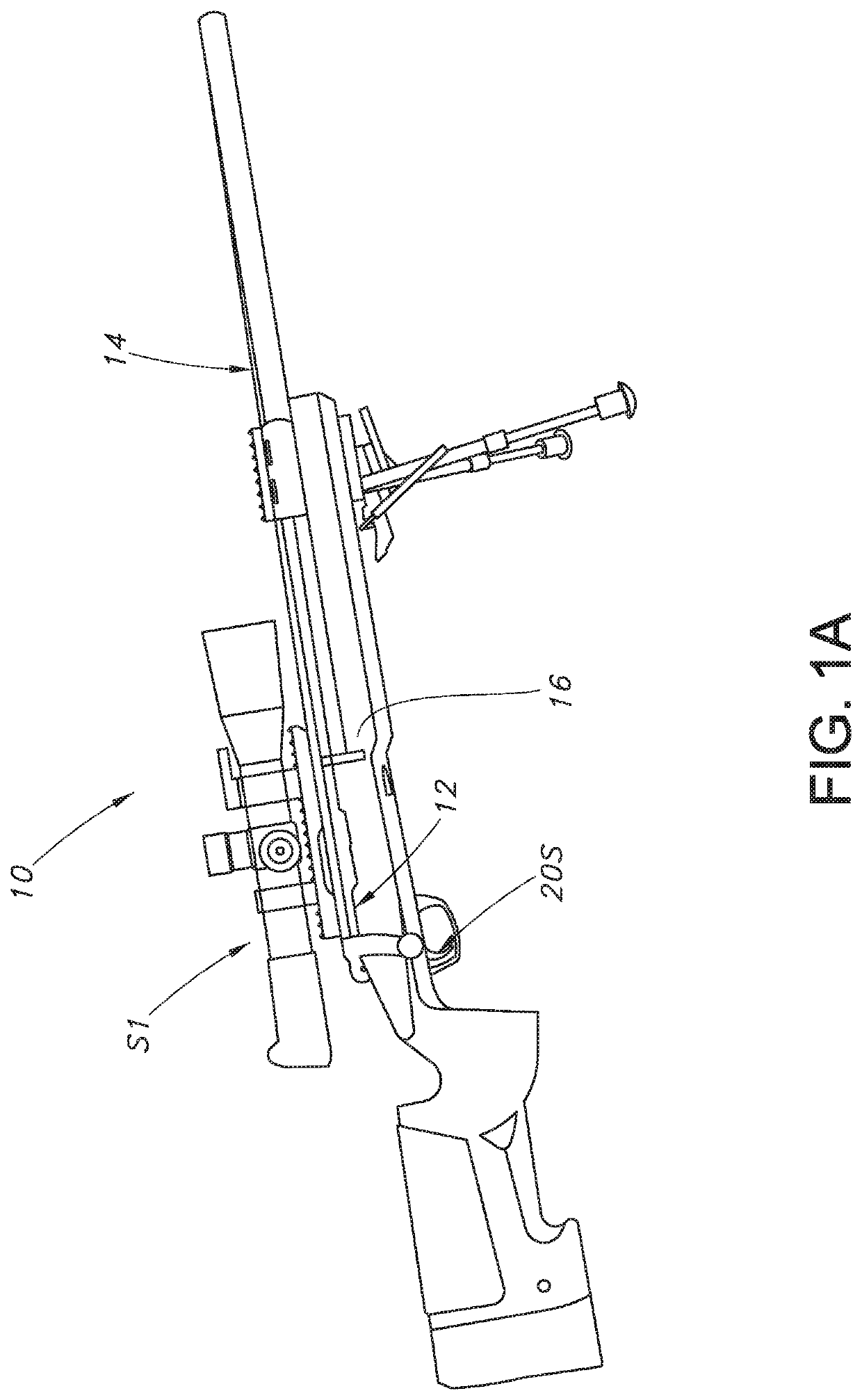
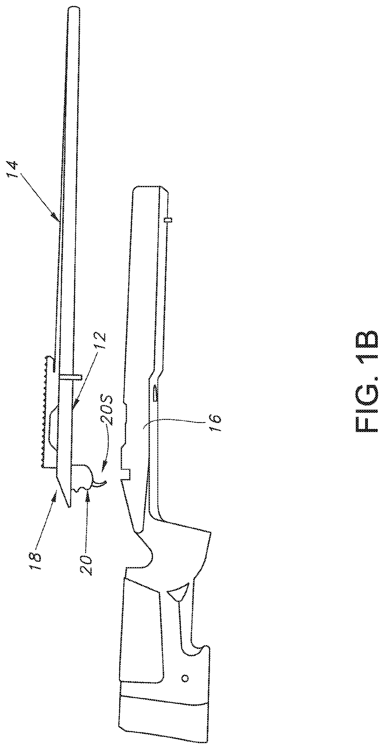
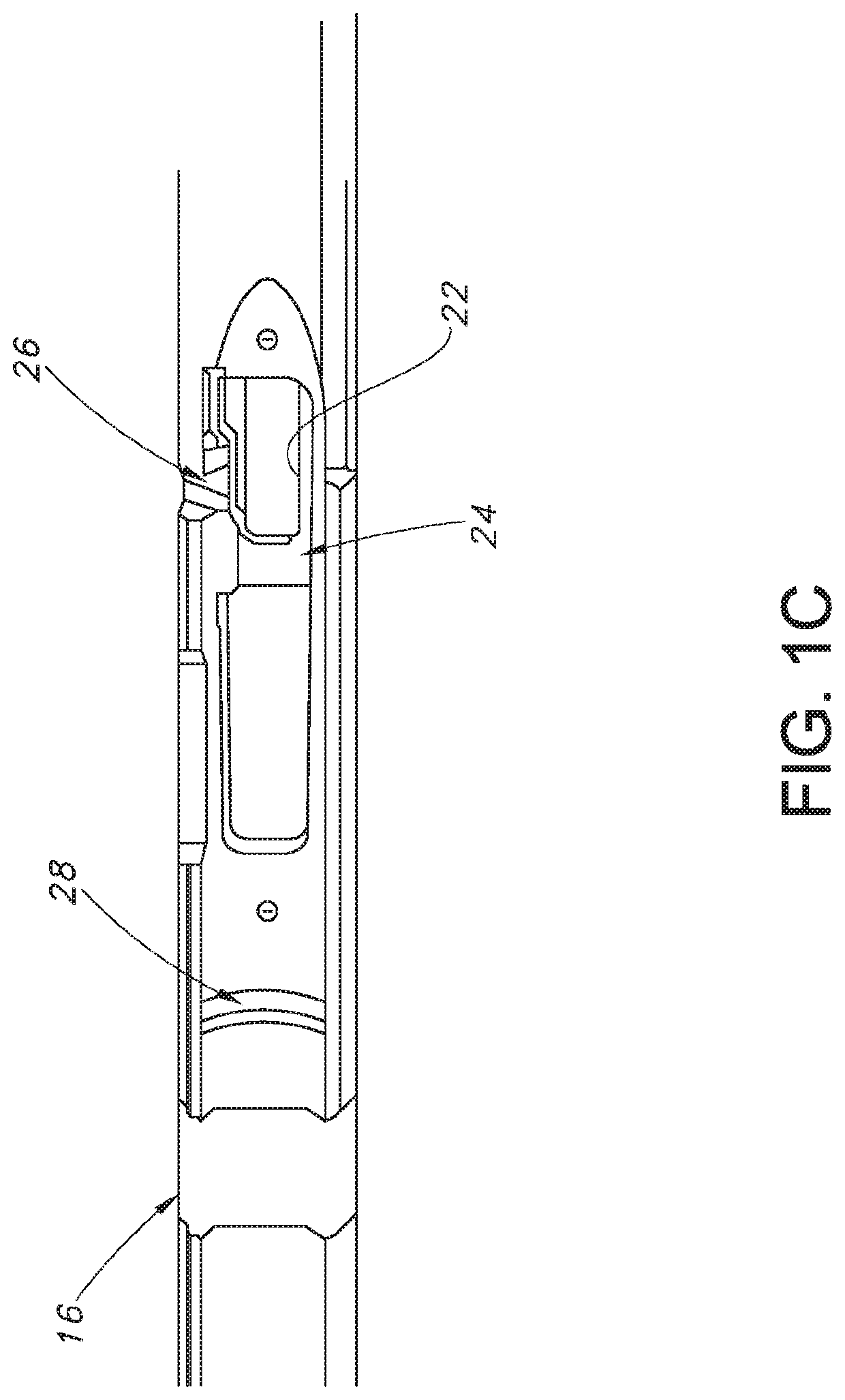
[0033]Turning now to a more detailed description of the present invention, FIGS. 1A-1C illustrate a standard prior art rifle 10 in which the standard trigger assembly 20 and the standard stock 16 may be modified to provide the advantages of the system and method of the present invention.

[0034]In accordance with the method and structure of the present invention, rifle system 310 has a robust and reliable trigger assembly 50 which can be used to enhance the ergonomics of trigger actuation and allow the shooter or user to tune or customize the trigger for his or her needs while also aiding in the use of electro-optical and other accessories (e.g., S1-S4) which may be mounted on or configured with the rifle system 310.

[0035]Rifle system 310 has at least one trigger motion sensor (e.g., 340L, 340R) which is proximate trigger assembly 50 when the receiver assembly 312 is installed in the stock (or chassis) 316. Referring to the exemplary embodiment of FIG. 6, Stock 316 has an open trough ...


PUM


Abstract

A rifle or portable firearm assembly (e.g., 310) configured to work with user-actuable sensors and systems (e.g., S1-S4), comprises a removable receiver assembly 312 attached to and responsive to a trigger assembly 50 which are removably received in a stock or chassis 316 having a middle section 324 with a trigger motion sensing sidewall segment with at least one trigger motion sensor (e.g., 340L, 340R) which does not physically contact or attach to the trigger assembly and is instead spaced from every component of the trigger assembly when the receiver is installed in said stock or chassis. The trigger motion sensor is configured to sense, from a selected standoff distance, without contacting or interfering the trigger assembly in any way, at least one of (a) the trigger's first stage movement or (b) actuation of a safety lever, and generate a “trigger motion sensed” signal in response thereto.

Description

PRIORITY CLAIM AND CROSS-REFERENCE TO RELATED APPLICATIONS[0001]This application is a continuation of and claims priority to U.S. provisional patent application no. 62 / 837,247, entitled “Non-Contact Electro-Magnetic Actuator and Method” which was filed on Apr. 23, 2019, the entire disclosure of which is incorporated herein by reference. The present application is also related to commonly owned application Ser. No. 14 / 462,348, filed Aug. 14, 2014, now U.S. Pat. No. 9,267,750, the entire disclosure of which is also incorporated herein by reference.BACKGROUNDField of the Invention[0002]The present invention relates to firearms and more particularly to trigger mechanisms for use in rifles and other manually actuable instruments which carry or are configured with electro-optic sensors, target designators or other electronic accessories when in use by a shooter.Discussion of the Prior Art[0003]Rifle marksmanship has been continuously developing over the last few hundred years, and now ref...

Claims


Application Information

Patent Timeline
Patent Type & Authority Patents(United States)
IPC IPC(8): F41A19/17F41A19/63F41A17/56F41A3/66F41A19/59
CPCF41A19/63F41A3/66F41A17/56F41A19/59F41A19/17F41A17/64F41A19/15F41A19/16F41A19/69
Inventor TUBB, GEORGE WYATTTUBB, G. DAVIDKENT, HOWARD
Owner SUPERIOR SHOOTING SYSTEMS INC
Why Eureka
Try Eureka