
Mail doubles detection and correction system

a detection and correction system technology, applied in the field of anti-double detection and correction systems, can solve the problems of unintentional pulling of the second mail piece along with the first mail piece, increased re-sorting costs for customers, and ineffective anti-double mechanisms, so as to reduce the feeder throughput and reduce costs. , the effect of effective detection and correction

Inactive Publication Date: 2011-01-13
NORTHROP GRUMMAN SYST CORP
View PDF8 Cites 7 Cited by
  • Summary
  • Abstract
  • Description
  • Claims
  • Application Information

AI Technical Summary

Benefits of technology

[0009]Some of the advantages that may be obtained by practicing the present invention include an ability to detect and correct mail doubles effectively without damaging the mail or decreasing feeder throughput, a reduction in costs associated with downstream processing of mail doubles, an ability to handle open, poly-wrapped and other types of mail, and compatibility with existing mail processing equipment.

Problems solved by technology

Often times a second mail piece is unintentionally pulled along with the first mail piece as a result of friction, electrostatic charges, adhesion, pressure or other forces acting on the mail stack.
This situation may not be detected until both mail pieces are much further in the mail delivery process, resulting in mishandling and additional cost to the customer for re-sorting.
However, existing anti-doubling mechanisms are not always effective and can damage certain types of mail, such as poly-wrapped, stapled and open mail.

Method used


Image

  • Mail doubles detection and correction system
  • Mail doubles detection and correction system
  • Mail doubles detection and correction system

Examples


Embodiment Construction

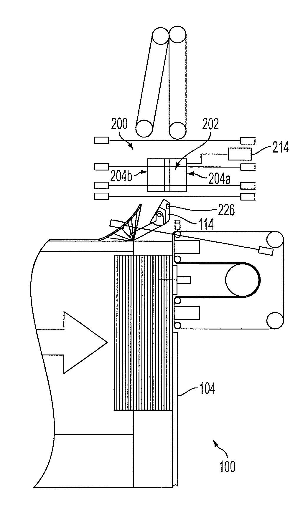
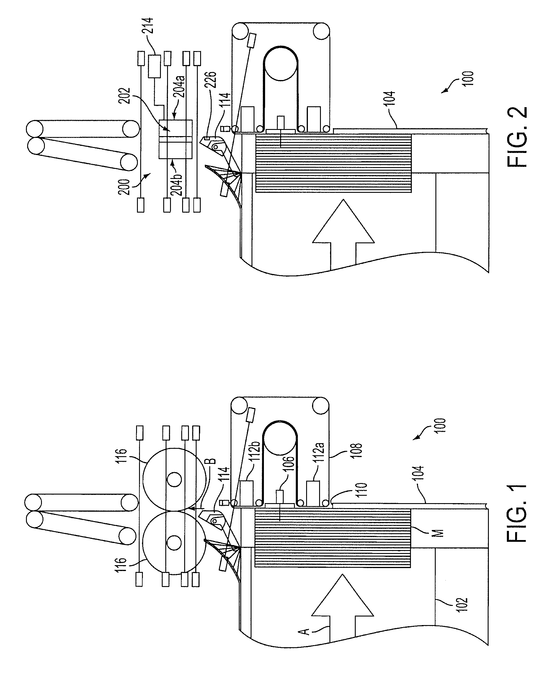
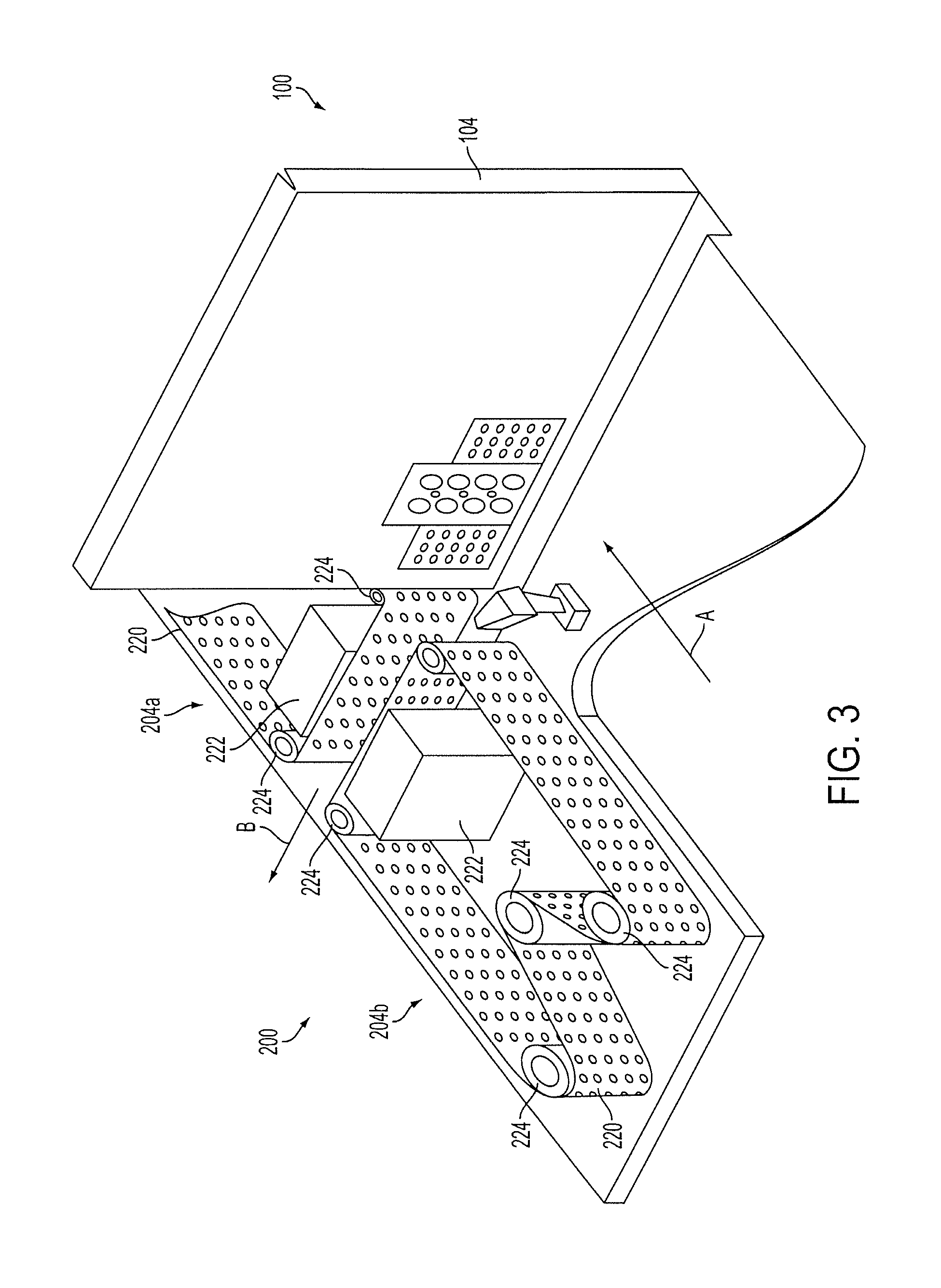
[0024]A mail doubles detection and correction system 200 according to an embodiment of the present invention is shown in relation to a mail feeder 100 in FIGS. 2 and 3. In this embodiment, the system 200 replaces the pinch wheels 116 of the otherwise conventional feeder 100. The system 200 includes a mail support 202 positioned downstream of the feeder 100 in alignment with the fixed anti-doubler 114 of the feeder and a pair of perforated vacuum belt assemblies 204a and 204b disposed on opposite sides of the mail support. Referring to the cross-sectional views in FIGS. 4 and 5, it can be seen that the system 200 includes a plurality of sensors 206, 208a &208b, 210a &210b, and 212a &212b, disposed about the channel 202 and the vacuum belt assemblies 204a &204b to detect the presence of one or more mail pieces M within a detection space S defined therebetween. A computerized controller 214 determines in real time whether one or more mail pieces are present in the detection space S bas...


PUM


Abstract

A mail doubles detection and correction system for a mail processing system with a feeder includes a mail support configured to support at least two mail pieces in a detection space downstream of the feeder, a pair of vacuum belt assemblies disposed on opposite sides of the detection space, and one or more sensors positioned about the detection space to detect a position of one or more mail pieces in the detection space. Each vacuum belt assembly includes a vacuum port facing the detection space and a perforated belt movable across the vacuum port in a mail transport direction. The system detects a mail double when the sensors indicate that more than one mail piece is disposed in the detection space and corrects the situation by moving one of the belts and holding the other belt stationary to advance only one of the mail pieces, and subsequently moving both of the belts to advance the remaining mail piece. The system detects a normal feed when the sensors indicate only one mail piece in the detection space, in which case both of the belts are moved to advance the mail piece. The system can also be configured to automatically adjust a width of the detection space to accommodate mail pieces having a range of widths.

Description

BACKGROUND OF THE INVENTION[0001]I. Field of the Invention[0002]The present invention relates generally to mail processing systems and, more particularly, to an anti-doubling detection and correction system for use in mail processing systems.[0003]II. Discussion of the Background Art[0004]Mail processing systems, such as mail sorters, typically include one or more feeders designed to singulate an individual mail piece from a stack of mail for downstream processing. FIG. 1 shows a top view of a mail feeder 100 for an automated mail sorting machine (AFSM) commonly used by the U.S. Postal Service. The mail feeder 100 includes a conveyor belt 102 with a horizontal run moving in a first direction A and a feeder plate 104 at a terminal end of the conveyor belt perpendicular to the horizontal run. Mail pieces M are stacked on edge in a generally vertical orientation on the conveyor belt 102 and moved in the first direction A toward the feeder plate 104. As the mail stack approaches the fee...

Claims


Application Information

Patent Timeline
Patent Type & Authority Applications(United States)
IPC IPC(8): B65H3/12
CPCB65H3/124B65H7/125B65H2404/261B65H2511/51B65H3/5246B65H2515/342B65H2553/412B65H2701/1916B65H2511/524B65H2220/01B65H2220/03B65H2220/02B65H2220/09B65H2515/34
Inventor CONAWAY, BRANT A.HILLERICH, THOMAS A.TIMM, JACOB L.
Owner NORTHROP GRUMMAN SYST CORP
Learn More