Microstrip antenna comprised of two slots

a microstrip antenna and slot technology, applied in the direction of antennas, antenna details, basic electric elements, etc., can solve the problems of reducing affecting the service life of the antenna, and affecting the overall size of the antenna

Inactive Publication Date: 2011-01-13
ELECTRONICS & TELECOMM RES INST +1
View PDF8 Cites 147 Cited by
  • Summary
  • Abstract
  • Description
  • Claims
  • Application Information

AI Technical Summary

Problems solved by technology

WLAN service based on 802.11b of a 2.4 GHz band has been assessed as having disadvantages in transmission rate, security, and interworking with a potable Internet service.
However, there is no significant problem to provide the service when the service is provided in a downtown location where an existing terrestrial network is well established, but there is a limitation when the service is provided in an area with restrictive acce

Method used


Image

  • Microstrip antenna comprised of two slots
  • Microstrip antenna comprised of two slots
  • Microstrip antenna comprised of two slots

Examples


Embodiment Construction

[0015]Although a few exemplary embodiments of the present invention have been shown and described, the present invention is not limited to the described exemplary embodiments, wherein like reference numerals refer to the like elements throughout.

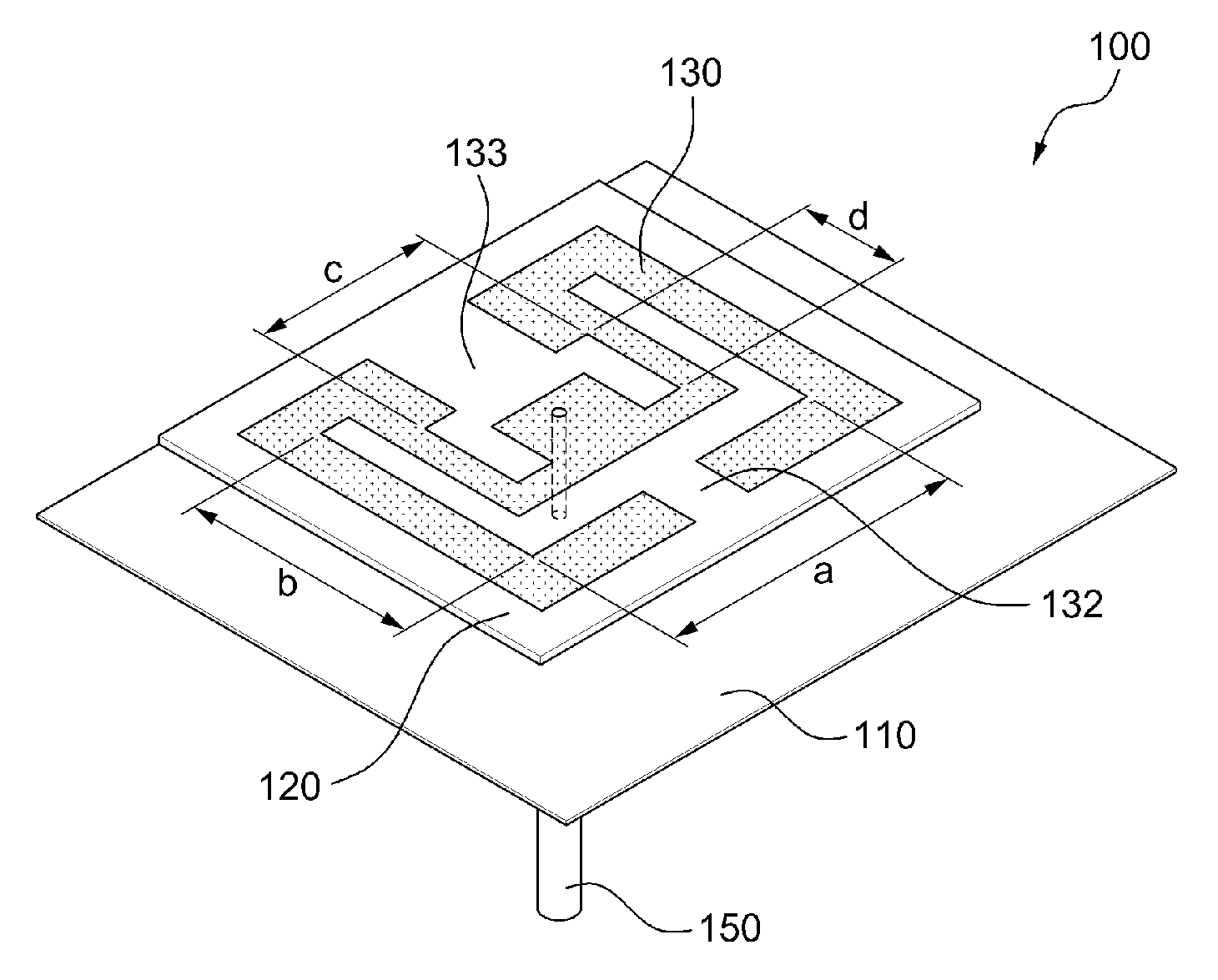
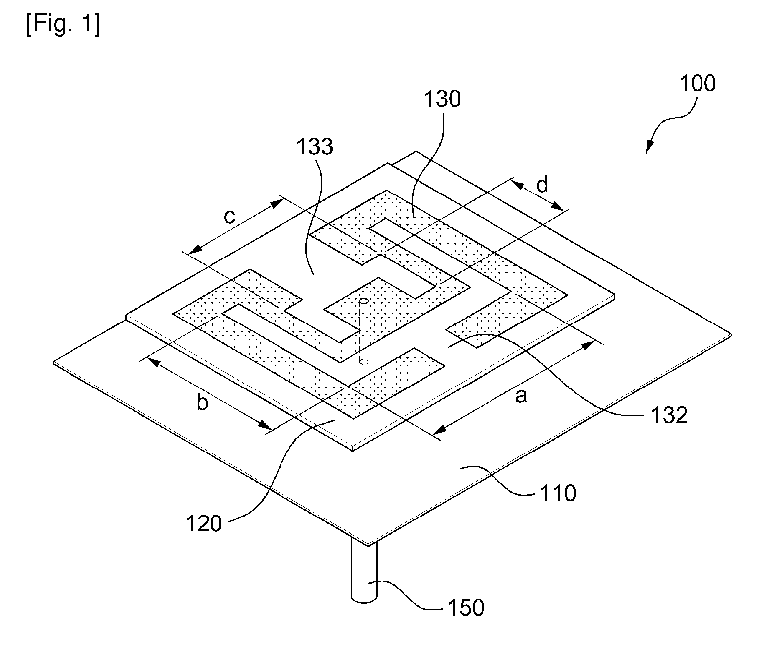
[0016]FIG. 1 is a perspective view illustrating a microstrip antenna including two slots and FIG. 2 is a divided perspective view of FIG. 1.

[0017]Referring to FIGS. 1 and 2, the microstrip antenna 100 includes a conductor plate 110, substrate 120, and coaxial line 150.

[0018]The conductor plate 110 includes a first hole 111 and serves as a ground connection.

[0019]The substrate 120 is located on a top of the conductor plate 110 and has a relative dielectric constant (εr) of 3.38 and a thickness of 0.508 mm. A certain interval between the conductor plate 110 and substrate 120 exists, thereby having a layer of air. The substrate 120 includes a microstrip patch 130 and a plurality of slots positioned in the microstrip patch 130.

[0020]The microstr...


PUM


Abstract

Disclosed relates to a microstrip antenna, particularly, relates to a dual band microstrip antenna including two slots. The microstrip antenna includes a conductor plate having a first hole and a substrate having a microstrip patch where slots of two different sizes are positioned, the substrate being located on a top of the conductor plate.

Description

TECHNICAL FIELD[0001]The present invention relates to a microstrip antenna, particularly, to a multiple-band microstrip antenna having two slots.[0002]This work was supported by the IT R&D program of MIC / IITA [2006-S-020-02, Development of Internet satellite wireless interlock of a high speed object].BACKGROUND ART[0003]A Wireless Local Area Network (WLAN) is a technology that enables the use of high speed Internet through a PDA, notebook, and computer within a certain distance around a location where a wireless access point is set. That is, the WLAN being free from a wired LAN can provide every advantage and function that the conventional wired LAN provides. WLAN service based on 802.11b of a 2.4 GHz band has been assessed as having disadvantages in transmission rate, security, and interworking with a potable Internet service. Conversely, a 5 GHz band based on IEEE 802,11a standard with high transmission rate recently attracts public attention. Therefore, requirement to include the...

Claims


Application Information

Patent Timeline
IPC IPC(8): H01Q9/04H01Q1/38
CPCH01Q9/0407H01Q5/357H01Q9/0442H01Q13/08H01Q1/38
Inventor PARK, IKMOKIM, BYOUNGCHULHAN, SUNG MINRYU, JOON GYUCHANG, DAE IGLEE, HO JIN
Owner ELECTRONICS & TELECOMM RES INST
Why Eureka
Try Eureka