Transmission line phase shifter with controllable high permittivity dielectric element

a dielectric element and transmission line technology, applied in waveguides, delay lines, antennas, etc., can solve the problems of high cost of steerable antennas, significant disadvantages of omnidirectional antennas, and one major disadvantage of phased array antennas, and achieve low cost. , the effect of low cos

Inactive Publication Date: 2006-04-11
MICROSOFT TECH LICENSING LLC
View PDF5 Cites 98 Cited by
  • Summary
  • Abstract
  • Description
  • Claims
  • Application Information

AI Technical Summary

Benefits of technology

[0016]As will be readily appreciated from the foregoing summary, the invention provides a low-cost transmission line phase shifter. The transmission line phase shifter is low cost because a common high-permittivity dielectric element is employed to control phase shift. Time delay (phase shift) control is provided by electromechanically controlling the interaction of the permittivity of the high-permittivity dielectric element on a wire transmission line. The permittivity interaction is controlled by controlling the position of the high-permittivity dielectric element with respect to the wire transmission line using?? a low-cost electromechanical device, such as a low-cost servo-controlled motor, a voice coil motor, etc., or by electrically controlling the permittivity of the high-permittivity dielectric element. Phased array antennas employing the invention are also low cost because such antennas are ideally suited for implementation in low-cost printed circuit board form.

Problems solved by technology

While omnidirectional antennas are inexpensive and widely used in environments where the direction of signal transmission and / or reception is unknown or varies (due, for example, to the need to receive signals from and / or transmit signals to multiple locations), omnidirectional antennas have a significant disadvantage.
However, in the past, steerable antennas have been expensive.
While phased array antennas have become widely used in many environments, particularly high value military, aerospace, and cellular phone environments, in the past phased array antennas have had one major disadvantage.
They have been costly to manufacture.
The high manufacturing cost has primarily been due to the need for a large number of variable time delay elements, also known as phase shifters, in the antenna element feed paths.
While the cost of phased array antennas can be reduced by sector pointing and switching phased array antennas, the pointing capability of such antennas is relatively coarse.
Because of their expense, in the past, phased array antennas have not been employed in low-cost wireless network environments.
As a result, the significant advantages of phased array antennas have not been available in low-cost wireless network environments.

Method used


Image

  • Transmission line phase shifter with controllable high permittivity dielectric element
  • Transmission line phase shifter with controllable high permittivity dielectric element
  • Transmission line phase shifter with controllable high permittivity dielectric element

Examples


first embodiment

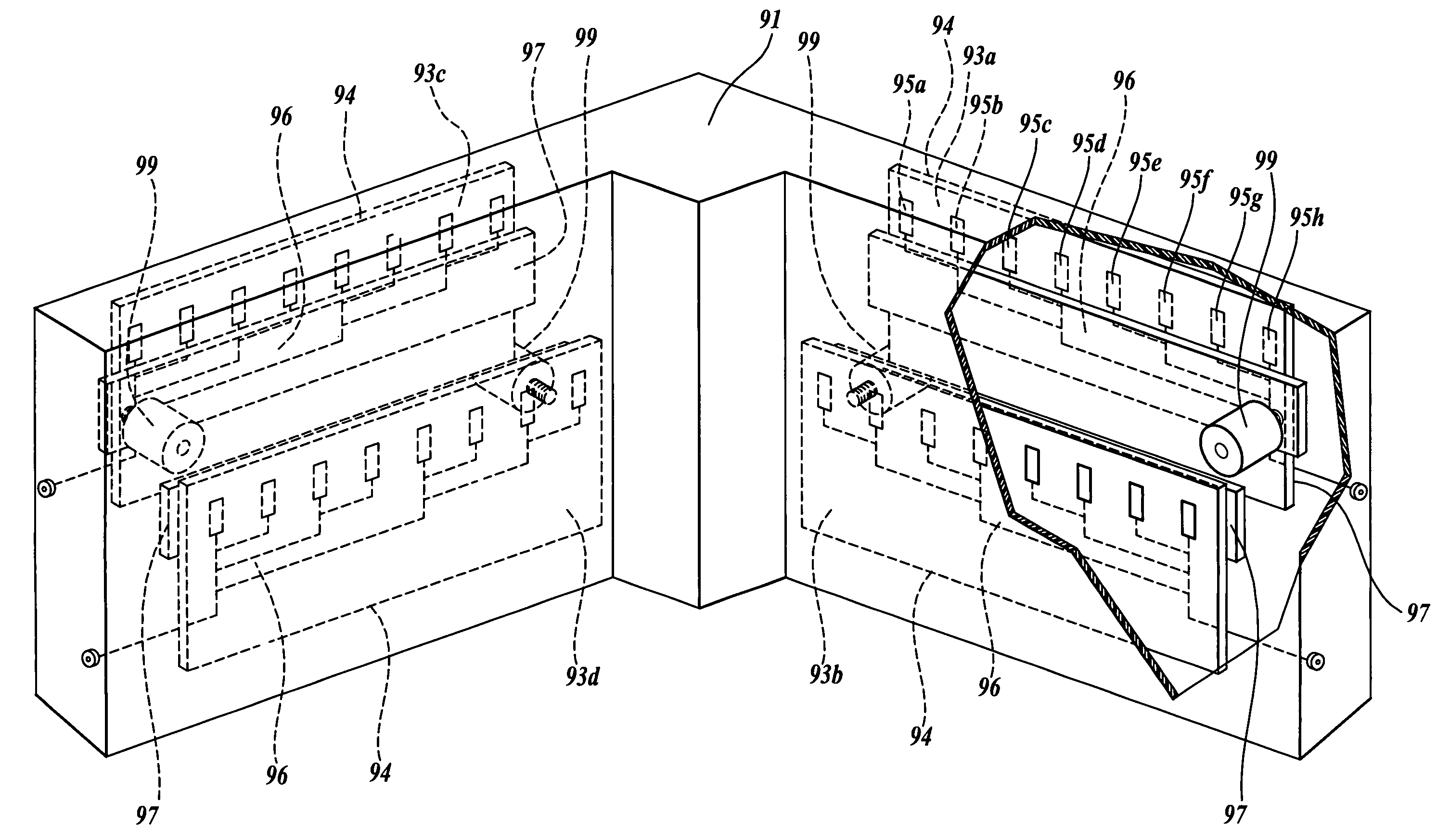
[0065]FIGS. 6–8 illustrate a 360° phased array antenna assembly embodying transmission line phase shifters formed in accordance with the present invention. The phased array antenna assembly includes an L-shaped housing 91. Located in each leg of the L-shaped housing are two back-to-back phased array antennas 93a, 93b, 93c, and 93d, each comprising eight linearly arrayed antenna elements and a corporate feed of the type illustrated in FIG. 5 and described above. More specifically, each of the phased array antennas includes a sheet of dielectric material 94, such as a printed circuit board (PCB) sheet. One of the PCB sheets 94 lies adjacent each of the four outer faces of the L-shaped housing 91. The outer surface of each of the PCB sheets includes a linear array of antenna elements, eight in the illustrated embodiment of the invention 95a–95h. Located on the inner surface of each of the PCB sheets 94 is a corporate feed 96 having the geometric layout illustrated in FIG. 5 and describ...

second embodiment

[0067]FIGS. 9–11 illustrate a low-cost, steerable, phased array antenna assembly embodying transmission line phase shifters formed in accordance with the invention that is somewhat similar to, but different from, the antenna assembly illustrated in FIGS. 6–8. Like the antenna assembly illustrated in FIGS. 6–8, the antenna assembly illustrated in FIGS. 9–11 includes an L-shaped housing 101. Each leg of the housing includes two linear phased array antennas pointing in opposite directions. However, rather than the phased array antennas being mounted on the outer facing side of a different PCB sheet and the corporate feed mounted on the inner facing side of the same PCB sheet, the antenna assembly illustrated in FIGS. 9–11 includes a single PCB sheet 102 in each of the legs, mounted such that both surfaces face outwardly. The elements 103c–103h of one of the linear phase array antennas are located on one face of the PCB sheet 102, and the elements 105a–105h of the other phased array ant...


PUM


Abstract

A transmission line phase shifter ideally suited for use in low-cost, steerable, phased array antennas suitable for use in wireless fidelity (WiFi) and other wireless telecommunication networks, in particular multi-hop ad hoc networks, is disclosed. The transmission line phase shifter includes a wire transmission line, such as a coaxial, stripline, microstrip, or coplanar waveguide (CPW) transmission line. A high-permittivity dielectric element that overlies the signal conductor of the wire transmission line is used to control phase shifting. Phase shifting can be electromechanically controlled by controlling the space between the high-permittivity dielectric element and the signal conductor of the wire transmission line or by electrically controlling the permittivity of the high-permittivity dielectric element.

Description

CROSS-REFERENCE TO RELATED APPLICATION[0001]This application is a continuation of application Ser. No. 10 / 738,684, filed Dec. 17, 2003, priority from the filing date of which is hereby claimed under 35 U.S.C. § 120.FIELD OF THE INVENTION[0002]This invention relates to phase shifters, and more particularly to phase shifting transmission lines.BACKGROUND OF THE INVENTION[0003]As will be better understood, the present invention is directed to transmission line phase shifters that are ideally suited for use in low-cost, steerable, phased array antennas. While ideally suited for use in low-cost, steerable, phased array antennas, and described in combination with such antennas, it is to be understood that transmission line phase shifters formed in accordance with this invention may also find use in other environments.[0004]Antennas generally fall into two classes—omnidirectional antennas and steerable antennas. Omnidirectional antennas transmit and receive signals omnidirectionally, i.e.,...

Claims


Application Information

Patent Timeline
Patent Type & Authority Patents(United States)
IPC IPC(8): H01P1/18H01Q3/36H01Q1/38H01Q3/30H01Q3/26H01Q3/32H01Q21/00H01Q21/08H01Q25/00
CPCH01P1/181H01P1/184H01Q3/32H01Q25/004H01Q21/0006H01Q21/08H01Q3/36
Inventor KAJIYA, JAMES T.
Owner MICROSOFT TECH LICENSING LLC
Why Eureka
Try Eureka