Spatially Selective UHF Near Field Microstrip Coupler Device and RFID Systems Using Device

a near field microstrip coupler and coupler technology, applied in the field of rfid systems, can solve the problems of “reading” and or “writing errors, increased system complexity, cost and delay response, and “blind” anti-collision managemen

Inactive Publication Date: 2005-03-03
ZIH CORP
View PDF26 Cites 89 Cited by
  • Summary
  • Abstract
  • Description
  • Claims
  • Application Information

AI Technical Summary

Problems solved by technology

When multiple passive transponders are within the range of the same RF transceiver electro-magnetic field they will each be energized and attempt to communicate with the transceiver, potentially causing errors in “reading” and or “writing” to a specific transponder in the reader field.
However, anti-collision management increases system complexity, cost and delay response.
Furthermore, anti-collision management is “blind” in that it cannot recognize where a specific transponder being processed is physically located in the RF electro-magnetic field, for example, which transponder is located proximate the print head of a printer-encoder.
This requires that the individual transponders have cumbersome shielding or a significant spatial separation.
The extra carrier substrate increases materials costs and the required volume of the transponder media bulk supply for a given number of transponders.
Having increased spacing between transponders may also slow overall printer-encoder throughput.
When transponders of different sizes and form factors are processed, the RF shielding and or anechoic chamber configuration will also require reconfiguration, adding cost, complexity and reducing overall productivity.
This may be very difficult to accomplish if the transponder also must be isolated in a shielded housing or chamber.
This creates issues for media suppliers by limiting the available space on the media 11 for transponder 1 placement and significantly increasing the necessary accuracy of the transponder 1 placement within and or under the printable media 11 and along the liner or carrier substrate 13.

Method used


Image

  • Spatially Selective UHF Near Field Microstrip Coupler Device and RFID Systems Using Device
  • Spatially Selective UHF Near Field Microstrip Coupler Device and RFID Systems Using Device
  • Spatially Selective UHF Near Field Microstrip Coupler Device and RFID Systems Using Device

Examples


Embodiment Construction

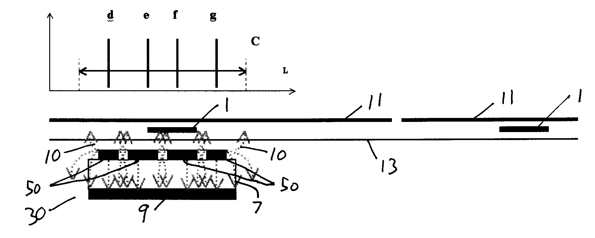
[0025] The present invention concerns apparatus and method which enables an RFID transceiver (sometimes termed herein an “interrogator”) to communicate selectively and exclusively with a single UHF transponder 1 when one or more other similar transponders are in close proximity, without the need for physical isolation or cumbersome shielded housings or chambers.

[0026] The invention is useful in the reading and or data loading of UHF transponders, for example on an assembly line, in distribution centers or warehouses where on-demand RFID labeling is required, and in a variety of other applications. In many applications a transponder or a number of transponders are mounted or embedded on or in a label, ticket, tag, card or other media carried on a liner or carrier. It is often desirable to be able to print on the media before, after, or during communication with a transponder. Although this invention is disclosed here in a specific embodiment for use with a direct thermal or thermal ...


PUM


Abstract

A system having a UHF RFID transceiver is adapted to communicate exclusively with a single electro-magnetically coupled transponder located in a predetermined confined transponder operating region. The system includes a near field coupling device comprising a plurality of lines connected in parallel with an unmatched load. The near field coupling device may be formed, for example on a printed circuit board with a plurality of electrically interconnected traces and a ground plane. The system establishes, at predetermined transceiver power levels, a mutual electro-magnetic coupling which is selective exclusively for a single transponder located in a defined transponder operating region. Also included are methods for selective communication with the transponder in an apparatus such as a printer-encoder.

Description

CROSS REFERENCE TO RELATED APPLICATIONS [0001] This application is a continuation-in-part of U.S. Utility Patent application No. 10 / 604,996, filed Aug. 29,2003 and hereby incorporated by reference in the entirety.BACKGROUND OF INVENTION [0002] 1. Field of the Invention [0003] The invention relates to RFID systems, operable with a variety of different dimensioned electro-magnetically coupled transponders, working at close proximity, to an RF transceiver antenna that is spatially selective for an individual transponder located in a predetermined transponder operating region to the exclusion of other adjacent transponders, and its application to printers-encoders or other systems utilizing such in UHF RFID systems. [0004] 2. Description of Related Art [0005] UHF radio frequency identification (RFID) technology allows wireless data acquisition and or transmission from and or to active (battery powered) or passive transponders using a backscatter technique. To communicate with, i.e., “re...

Claims


Application Information

Patent Timeline
Patent Type & Authority Applications(United States)
IPC IPC(8): G06K1/12G06K7/00G06K7/08G06K7/10
CPCG06K1/12G06K7/0008G06K7/10079G06K7/10366G06K7/10346G06K17/0025G06K7/10336
Inventor TSIRLINE, BORIS Y.HOHBERGER, CLIVE P.GAWELCZYK, ROBERTDONATO, DANIEL
Owner ZIH CORP
Why Eureka
Try Eureka