
Baylyn antenna mounting apparatus and system

a technology of antenna mounting and apparatus, applied in the field of marine antenna mounting, can solve the problems of antenna failure, antenna damage, removal and replacement of the entire antenna system,

Inactive Publication Date: 2011-01-13
GADBERRY RAYMOND
View PDF23 Cites 11 Cited by
  • Summary
  • Abstract
  • Description
  • Claims
  • Application Information

AI Technical Summary

Benefits of technology

"The present invention is a mounting apparatus for marine antennas that allows for easy installation and replacement of damaged antennas without the need for a complete overhaul of the entire system. The mounting apparatus includes a base mount and an upper barrel assembly that can be locked in multiple positions. The system also includes a primary and secondary conductive path for signal transmission. The invention eliminates the need for costly professional services to remove and replace antennas and cabling / wiring, and it provides better protection against corrosion and damage to the antenna and its internal components. The technical effects of the invention include quicker and easier installation, reduced cost, and improved protection against corrosion and damage."

Problems solved by technology

Due to the unforgiving nature of the fixed position, variable position, or any other type of mount, antennas are often damaged when passing underneath low lying structures.
The effects of the damage can often result in antenna failure.
This failure is often due to a bad connection or a faulty or damaged antenna.
However, due to the antenna failure, the owner of the vessel often must remove and replace the entire antenna system.
Such removal, replacement, or repair can be costly to the owner because it typically requires a technician for the removal, installation, and repair of the antenna mounting system.
Although in-line splitters may be used to mitigate the cost of replacement, these often change the impedance of such antenna systems and are typically installed incorrectly.
When in-line splitters are installed incorrectly, the purchase of a whole new system is often required.
In addition, a further problem in this field is that the antenna and its internal components are often exposed to the elements.
The quality, and therefore the expense of the antenna often determines how well the antenna and its internal components are protected from moisture and the elements resulting in corrosion within the antenna housing.

Method used


Image

  • Baylyn antenna mounting apparatus and system
  • Baylyn antenna mounting apparatus and system
  • Baylyn antenna mounting apparatus and system

Examples


Embodiment Construction

[0032]The features of the present invention disclosed in the specification, the claims and / or in the accompanying drawings, may, both separately, and in any combination thereof, be material for realizing the invention in various forms thereof. Reference to the drawings are for the purposes of illustrating the embodiments of the invention only, and not for limiting of the same and its application or its usage.

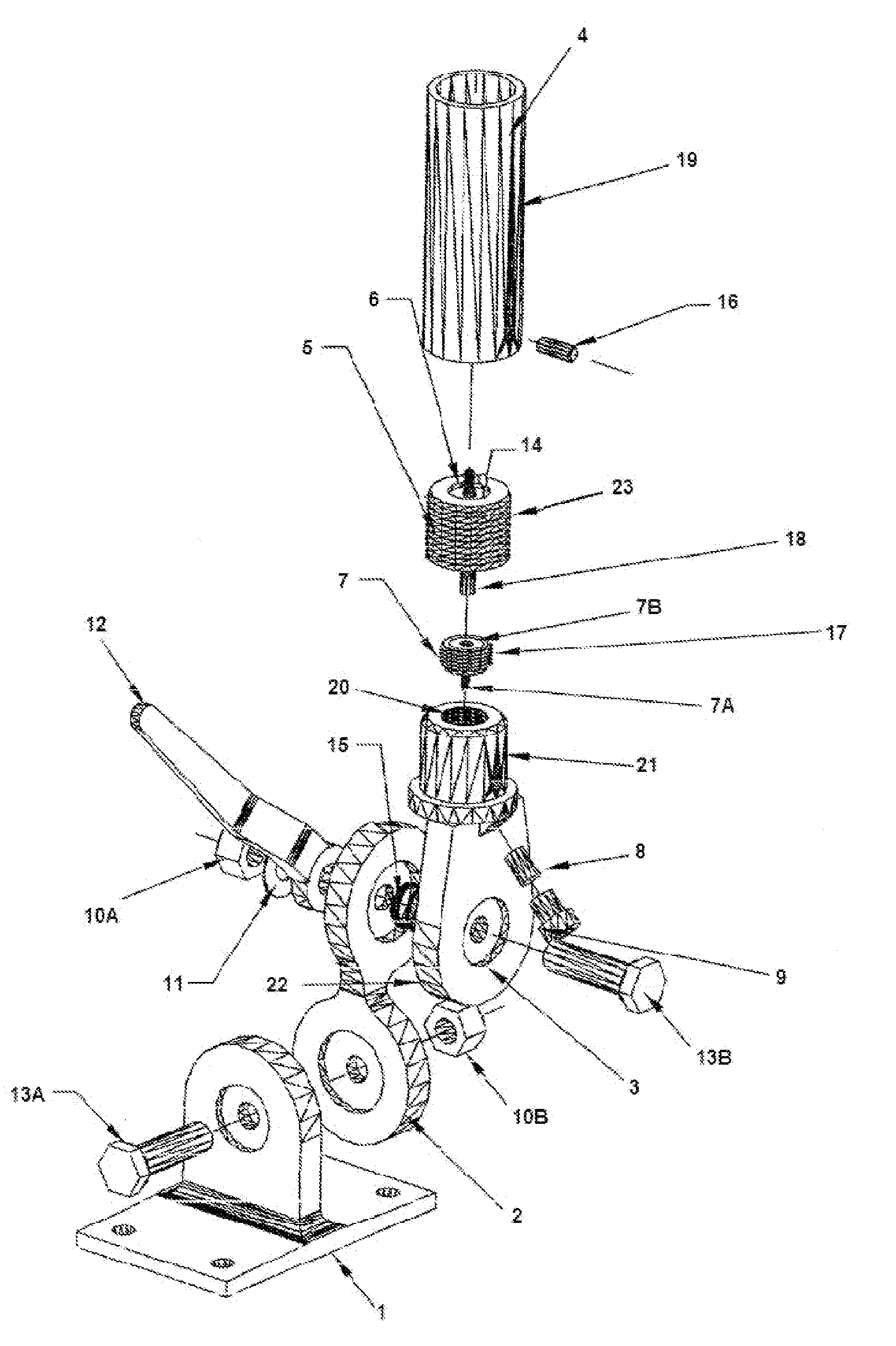
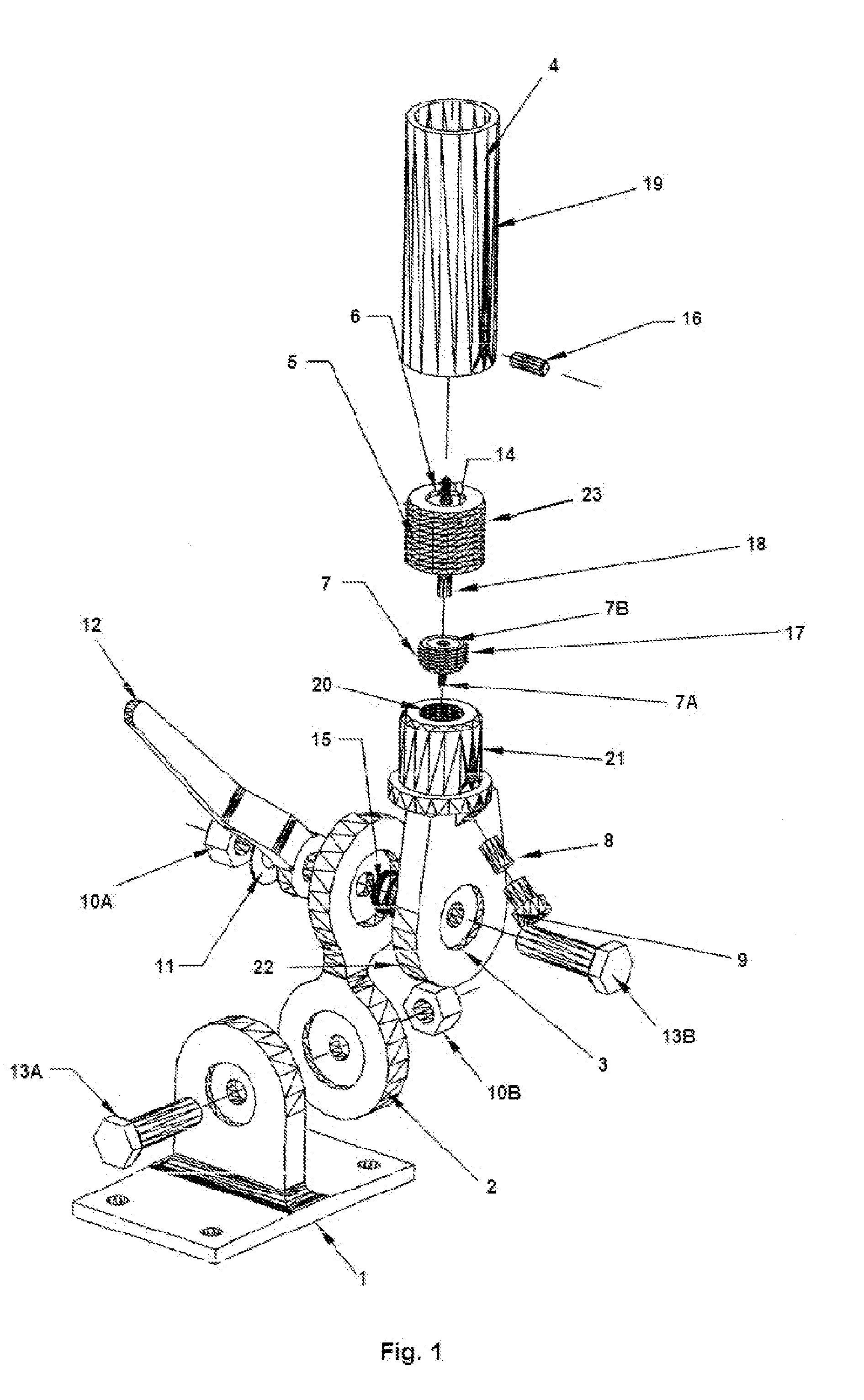
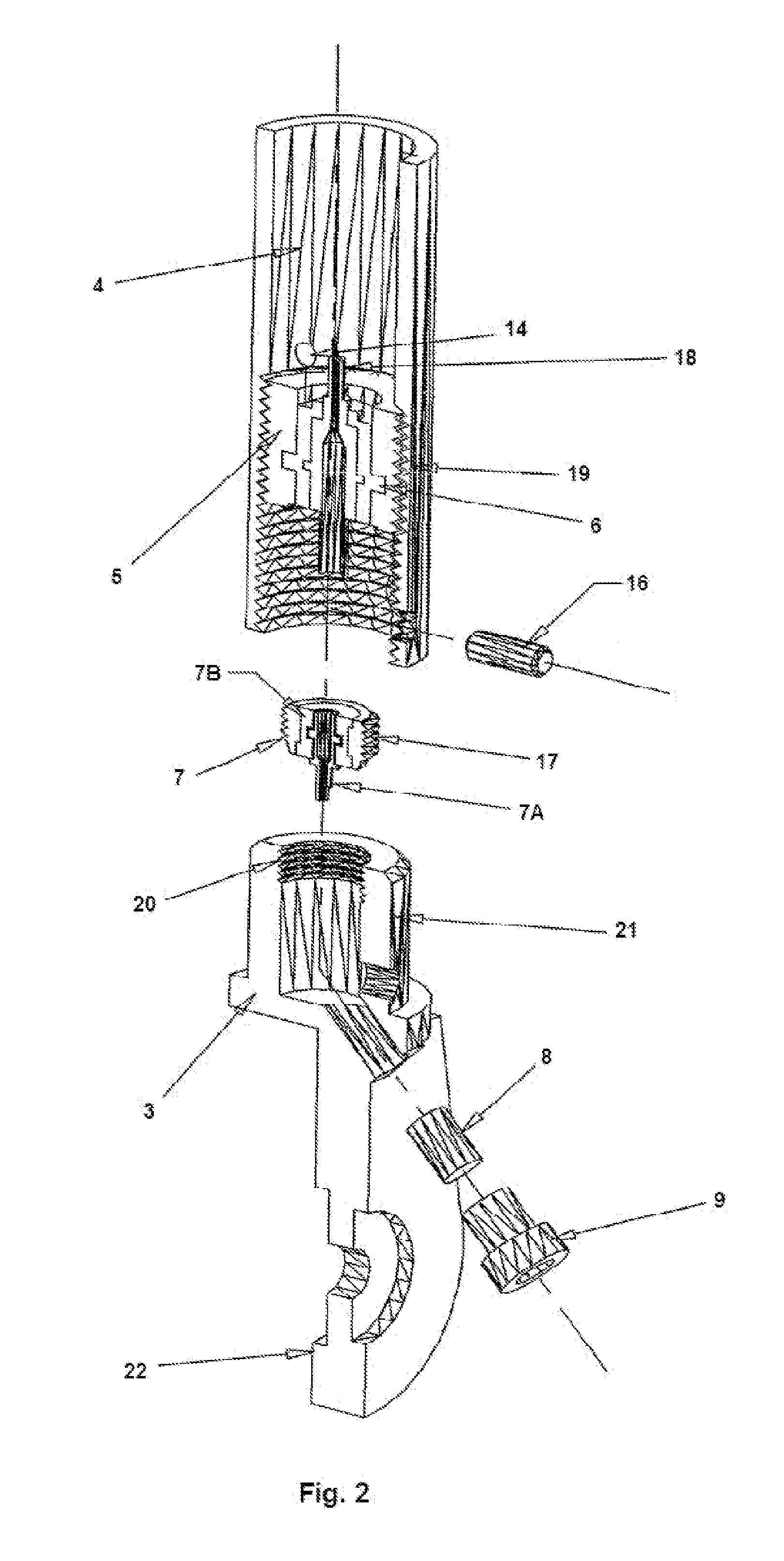
[0033]FIG. 1 illustrates an exploded breakdown of an exemplary aspect of the present invention incorporated with an existing mount as a reference only, and not to limit its application and usage thereof. A pedestal mounting base 1 with an upstanding semi-circular, notched or gear mesh ridged upper head is adjoined to the lower notched or gear mesh ridged pivotal head of a two axis pivotal point 2 by a bolt 13A that is inserted through the bore of the pedestal mounting base 1.

[0034]The bolt 13A is also inserted through the bore of the lower portion of the two axis notched or gear...


PUM


Abstract

An antenna mounting apparatus and system is provided for quick and easy installation and removal of antennas that can be utilized with mounting devices and systems. The present apparatus and system allows for a one time routing of transmission medium from the antenna mount, by attaching to a rotatable female connector within the base of the mount, thereby allowing the cable to move freely. This prevents loss of connection as the connector is threaded into the male portion of the upper mount assembly. The barrel assembly may contain a male pin connector threaded within the chamber of the barrel connected to the antenna. The female barrel assembly may then thread onto the male lower assembly where the male and female connectors will adjoin, thus creating a solid connection point with the set screw which will serve to eliminate a loss of conductive connection and reduce theft.

Description

BACKGROUND[0001]1. Field of the Invention[0002]The present invention relates generally to marine antenna mounts for watercraft, recreational vehicles and the like. More specifically, the present invention relates to a mounting apparatus and system that provides for the quick and simple installation of antennas and the quick and simple removal of damaged antennas.[0003]Antennas and associated mounting systems are commonly mounted externally and vertically on watercraft, recreational vehicles and the like. The external and vertical mounting usually affords antennas a more suitable range and propagation path for sending and receiving signals.[0004]Numerous applications and advantages may be utilized by the present antenna mounting apparatus and system, for example, with vertical, fixed, or variable position mounts, and so forth. In addition, the improved mounting apparatus and system may be compatible with, but not limited to, commonly used transmission media such as coaxial cable and / ...

Claims


Application Information

Patent Timeline
Patent Type & Authority Applications(United States)
IPC IPC(8): H01Q3/02F16M13/00
CPCH01Q1/084H01Q1/34H01Q1/1207H01Q1/088
Inventor MORROW, KEVIN ALLEN
Owner GADBERRY RAYMOND
Learn More