PWM Control Device and Driving Method thereof

Inactive Publication Date: 2011-01-13
GIGA BYTE TECH CO LTD
View PDF3 Cites 4 Cited by
  • Summary
  • Abstract
  • Description
  • Claims
  • Application Information

AI Technical Summary

Benefits of technology

[0008]From the aforementioned PWM control device and the driving method thereof, it can be understood that the total output phase number will be properly selected according to the load capacity, and the output phases will be selected

Problems solved by technology

Thus, the failure rate of the enabled d

Method used


Image

  • PWM Control Device and Driving Method thereof
  • PWM Control Device and Driving Method thereof
  • PWM Control Device and Driving Method thereof

Examples


Example

[0015]Reference will now be made to the drawings to describe exemplary embodiments of the present invention, in detail. The following description is given by way of example, and not limitation.

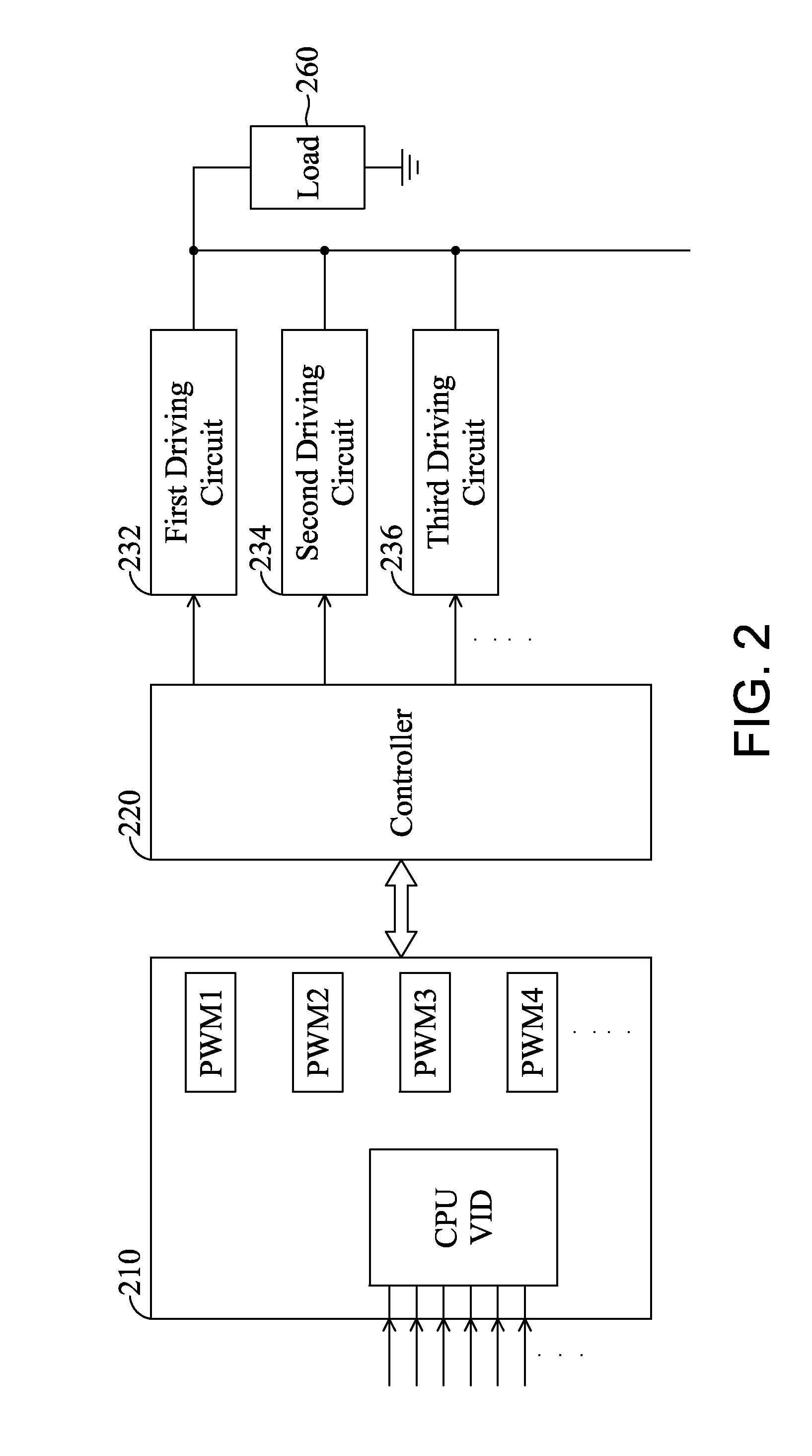
[0016]FIG. 2 shows a structure of a PWM control device in accordance with an embodiment of the present invention. The PWM control device comprises a PWM device 210 and a controller 220.

[0017]The PWM device 210 may be a chip, an integrated circuit (IC) or a microprocessor for providing multi-phase PWM signals. The controller 220 is electrically connected to the PWM device 210 and a plurality of driving circuits for receiving PWM signals from the PWM device 210. After operating and processing the received PWM signals, the controller 220 respectively transmits the processed PWM signals to the first driving circuit 232, the second driving circuit 234 and the third driving circuit 236, etc. Thus, the control intention of the present invention is achieved. The controller 220 may also be a chip, an i...


PUM


Abstract

In a pulse width modulation (PWM) control device and driving method, the PWM control device includes a PWM device, for providing a plurality of PWM signals; and a controller electrically connected to the PWM device and a plurality of driving circuits, for controlling PWM signals to arbitrarily enable or disable the plurality of driving circuits according to load capacity; wherein when driving circuits are damaged, the controller disables the damaged driving circuits and replaces the damaged driving circuits with the other driving circuits.

Description

BACKGROUND[0001]1. Technical Field[0002]The present invention relates to a control device and, more particularly, to a pulse width modulation (PWM) control device.[0003]2. Description of the Related Art[0004]FIG. 1 shows a structure of a conventional PWM control circuit. The PWM control circuit comprises a PWM device 110, driving circuits 132 and 134. Generally speaking, when changing the total output phase number, the PWM device 110 (or PWM integrated circuit) will increase or decrease the total output phase number gradually. In addition, the PWM device 110 will select some of the phases as output phases according to a fixed sequence. When the load capacity is heavy, most of the driving circuits will output current to the load 160; when the load capacity is light, only some of the driving circuits will be selected to output current, and the selected driving circuits is predetermined. Thus, those predetermined driving circuits will always output current to the load 160. For example,...

Claims


Application Information

Patent Timeline
IPC IPC(8): H02M1/08
CPCH02M3/1584Y02B70/16H02M2001/0032H02M1/0032Y02B70/10
Inventor LIAO, TSE-HSINEHUNG, JU-YI
Owner GIGA BYTE TECH CO LTD
Why Eureka
Try Eureka