
Drain pump

a technology of pump and water pump, which is applied in the direction of liquid fuel engines, machines/engines, combination engines, etc., can solve the problems of increased cavitation noise, increased vibration, and increased vibration of water pump, and achieve the effect of reducing the operation sound

Active Publication Date: 2011-01-13
FUJIKOKI CORP
View PDF4 Cites 13 Cited by
  • Summary
  • Abstract
  • Description
  • Claims
  • Application Information

AI Technical Summary

Benefits of technology

[0016]An object of the present invention is to provide a drain pump which is capable of reducing noise and vibration accompanying with the water scooping of a rotary impeller while maintaining pump performance, such as a head and the amount of discharged water.
[0017]Further, another object of the invention is to provide a drain pump that reduces noise by modifying the shape of an outer portion of an upper edge portion of a cylindrical wall member of a rotary impeller.
[0019]According to the drain pump of the invention, the large-diameter blade is divided into the inner and outer blades, and the inner and outer blades are alternately disposed around the shaft portion, so that air bubbles may be escaped to the downstream side in the rotational direction through gaps between the inner and outer blades, gaps between the inner blades and the ring member, and gaps between the outer blades and the shaft portion. Accordingly, the amount of air bubbles colliding with the large-diameter blades is decreased and noise caused by the burst of air bubbles may be decreased. Further, since a force applied to the large-diameter blade in a direction opposite to the rotational direction is decreased, a load is decreased and vibration is reduced. If a distance R2 between the center of the shaft portion and an inner end of the outer blade in the radial direction is set to be substantially equal to a distance R1 between the center of the shaft portion and an outer end of the inner blade in the radial direction, the length of the large-diameter blade of the invention, which scoops up water, in the radial direction is substantially equal to the length of the large-diameter blade in the related art in the radial direction. Accordingly, it may be possible to secure the same pump performance as that of the drain pump in the related art. Further, if the area of the opening of the inlet and the area of the flow passage of the drain pump according to the invention are set to be substantially equal to those of the drain pump in the related art, it may be possible to secure the same amount of discharged water as that of the drain pump in the related art.
[0021]According to the drain pump of the invention, it may be possible to reduce the operation sound such as water scooping sound.

Problems solved by technology

This collision causes vibration or noise of the scooping of water.
For this reason, cavitation noise and vibration are increased.
Further, when air bubbles, which are generated at the time of the start-up of the drain pump by the water scooping of the blade, collide with the inner wall of the housing and burst, cavitation noise is generated.
However, the more efficient reduction of noise has not been particularly considered.

Method used


Image

  • Drain pump
  • Drain pump
  • Drain pump

Examples


Embodiment Construction

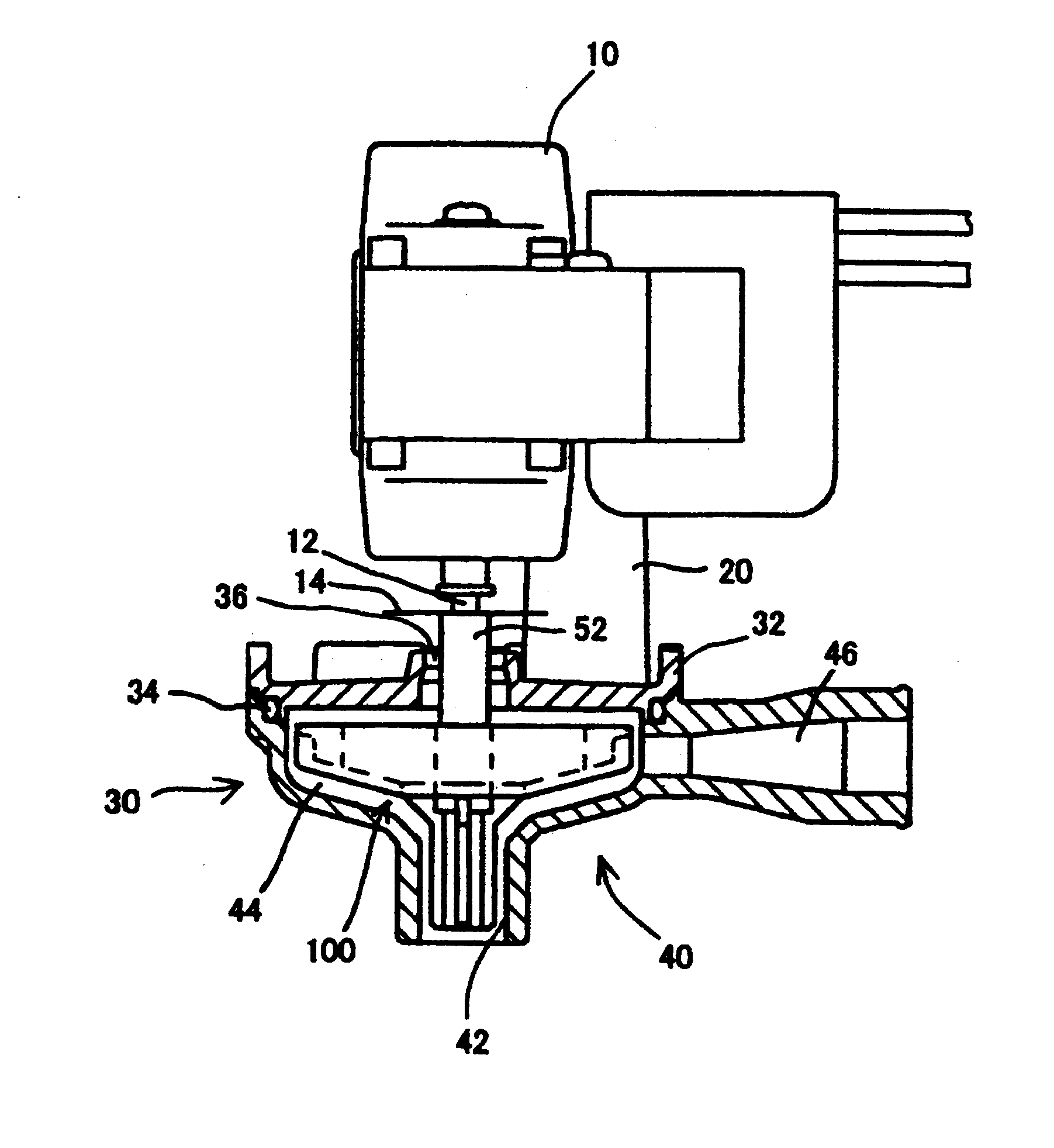
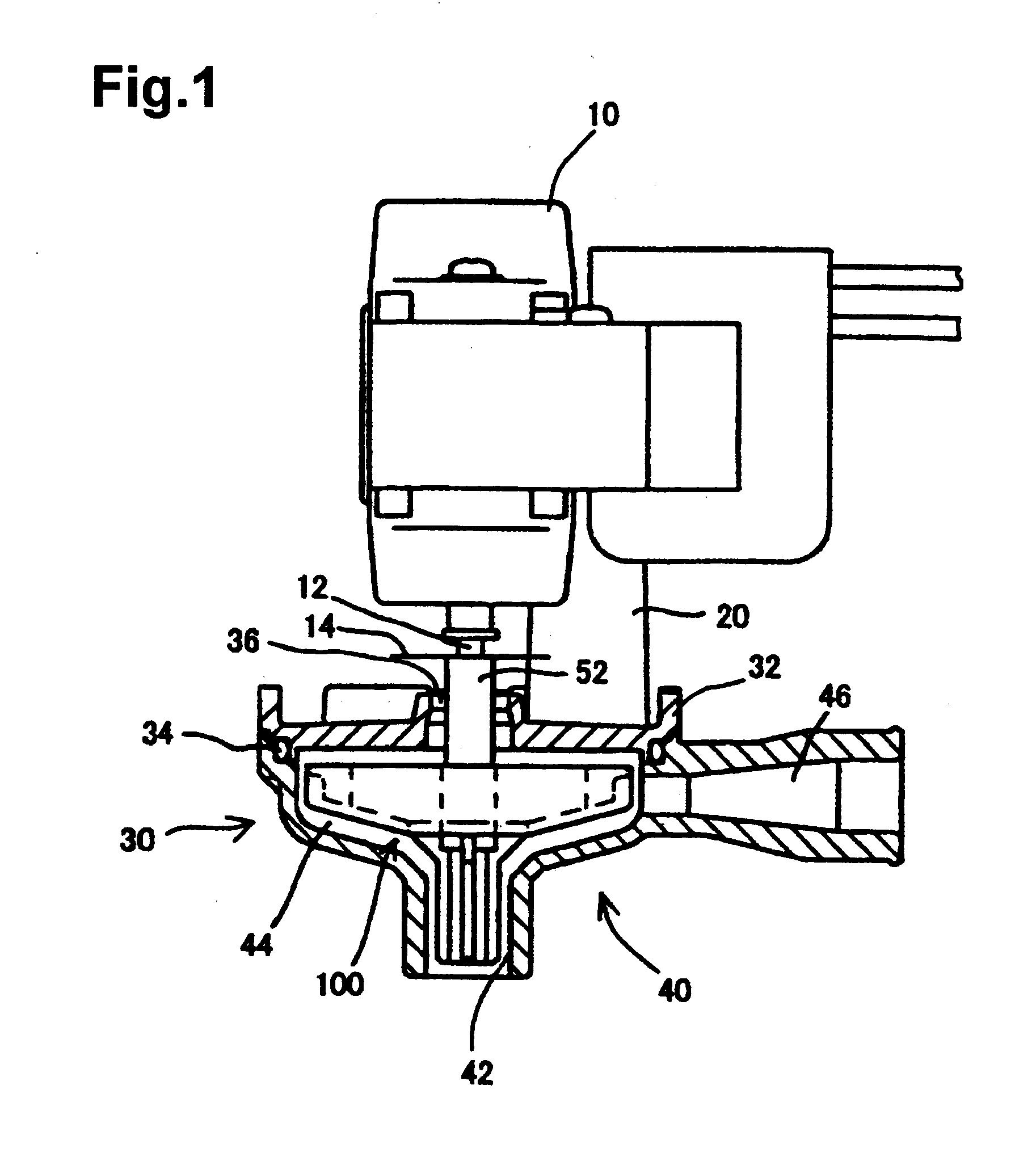
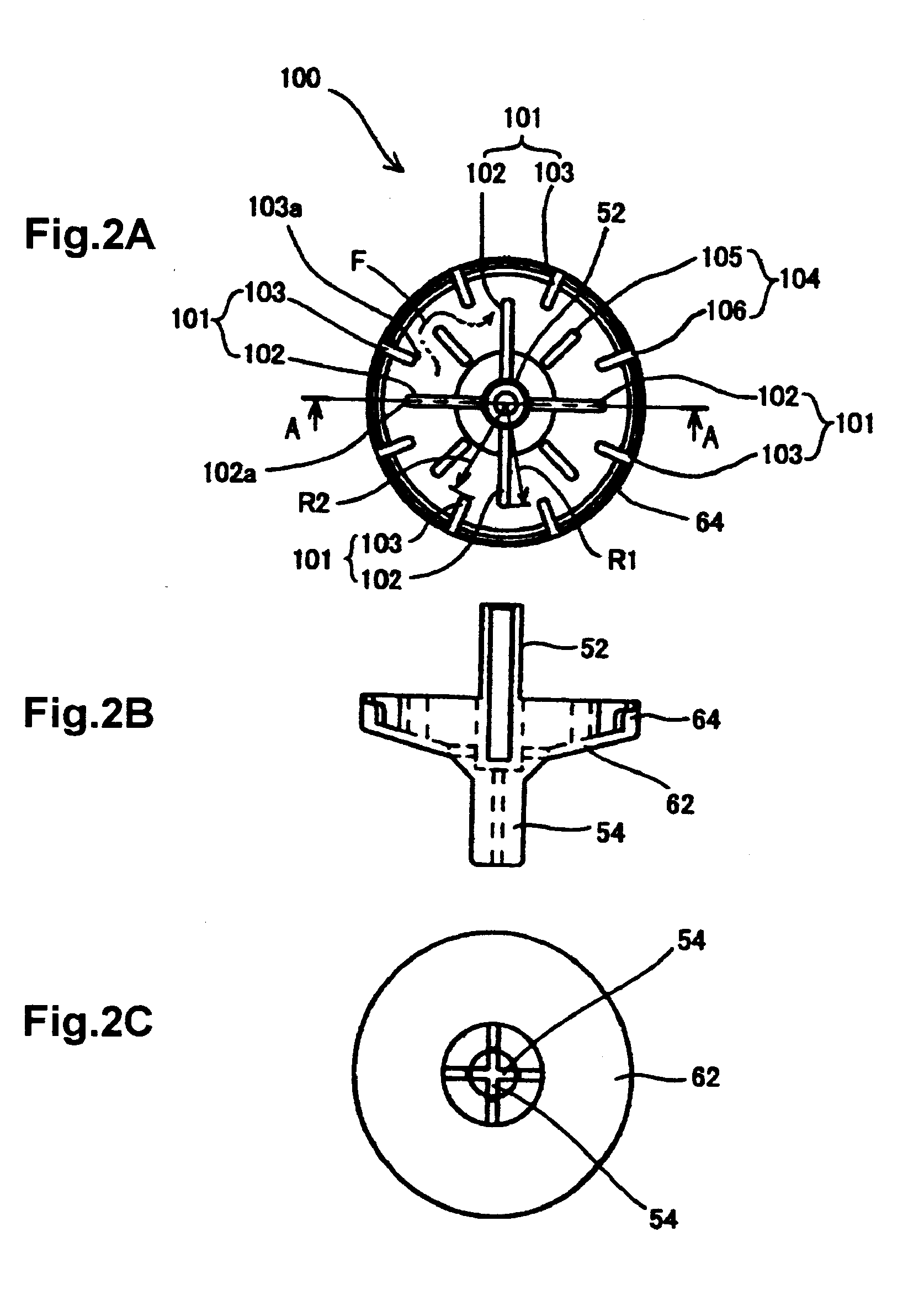
[0048]Embodiments of a drain pump according to the invention will be described below with reference to drawings. FIG. 1 is a front view showing the partial cross-section of an example of a drain pump according to the invention, and FIG. 2 shows an embodiment of a rotary impeller used in the drain pump shown in FIG. 1. FIG. 2A is a top view of the rotary impeller. FIG. 2B is a cross-sectional view of the rotary impeller shown in FIG. 2A, taken along a line A-A of FIG. 2A. FIG. 2C is a bottom view of the rotary impeller shown in FIG. 2A. The same components of the drain pump, which is provided with the rotary impeller, as those of the drain pump shown in FIGS. 22 and 23 are denoted by the same reference numerals, and the description thereof will not be repeated. Further, the same components of the rotary impeller except for the components of the rotary impeller, which shows characteristics of the invention, as those of the rotary impeller shown in FIGS. 22 and 23 are also denoted by t...


PUM


Abstract

A drain pump that maintains pump performance and reduces noise and vibration accompanying water scooping of a rotary impeller includes a large-diameter blade divided into an inner blade and an outer blade. A radius of an impeller scooping up water is the sum of the lengths of the inner and outer blades in a radial direction. The large-diameter blade is divided at a position where the amount of generated air bubbles is large, and the inner and outer blades are alternately disposed. Accordingly, air bubbles are escaped to a downstream side in a rotational direction, so that the intensity of the collision between the blades and air bubbles is decreased reducing noise caused by the burst of air bubbles and vibration caused by a collision load of the flow of a gas-liquid mixture.

Description

[0001]The present application is based on and claims priorities of Japanese patent applications No. 2009-161143 filed on Jul. 7, 2009 and No. 2009-219512 filed on Sep. 24, 2009, the entire contents of which are hereby incorporated by reference.BACKGROUND OF THE INVENTION[0002]1. Field of the Invention[0003]The present invention relates to a drain pump provided in, particularly, an air-conditioner.[0004]2. Description of the Related Art[0005]Moisture in the air is condensed and attached to a heat exchanger during a cooling operation of an indoor unit of an air-conditioner, and water droplets drop into a drain pan provided below the heat exchanger. A drain pump is provided in the indoor unit in order to drain away drain water stored in the drain pan. An example of the drain pump, there is a drain pump where an inlet is formed at a lower end portion of a housing, an outlet is formed at a side portion of the housing, a rotary impeller is rotatably provided in the housing, a motor is fix...

Claims


Application Information

Patent Timeline
IPC IPC(8): F04D13/12
CPCF04D13/06F04D29/669F04D29/24F04D1/14F04D11/00F04D29/18F04D29/663
Inventor KATO, YUYANEMOTO, SHINICHIYAMABIRAKI, KENJISATO, KATSUSHI
Owner FUJIKOKI CORP
Learn More