Sealing Arrangement for Turbine Engine Having Ceramic Components

Inactive Publication Date: 2011-01-13
SIEMENS ENERGY INC
View PDF8 Cites 8 Cited by
  • Summary
  • Abstract
  • Description
  • Claims
  • Application Information

AI Technical Summary

Benefits of technology

[0009]In accordance with a first aspect of the present invention, a seal arrangement is provided for reducing seal gaps within a turbine engine including a circumferentially extending structure having an axially extending surface forming a gas flow path extending parallel to an axis of the turbine engine. The seal arrangement comprises a plurality of circumferentially disposed segments defining the circumferentially extending structure. Each segment including an axially forward circumferential edge, an axially aft circumferential edge, and a pair of circumferentially spaced axial edges extending between the forward and aft edges. A surface portion comprising a portion of the axially extending surface extends between the forward and aft circumferential edges and between the pair of axial edges, the surface portion extending generally parallel to the axis of the turbine engine in contact with high velocity gases flowing therethrough, and each axial edge comprising a radial surface extending radially from the surface portion. The segments are arranged such that a gap is defined between facing axial edges of adjacent ones of the segments. A sealing element extends within the gap from the surface portions of the adjacent segments radially along at least a portion of the facing axial edges. The sealing element comprising a compliant material in the circumferential direction to span the gap during reduction and expansion of the gap. The sealing element is non-homogeneous and includes a first layer and a second layer. At least a portion of the second layer defines a protective erosion resistant surface located adjacent to and spanning between the surface portions of the adjacent segments.
[0010]In accordance with a second aspect of the present invention, a seal arrangement is provided for reducing seal gaps within a turbine engine including a circumferentially extending structure having an axially extending surface forming a gas flow path extending parallel to an axis of the turbine engine. The seal arrangement comprises a plurality of circumferentially disposed segments defining the circumferentially extending structure. Each segment includes an axially forward circumferential edge, an axially aft circumferential edge, and a pair of circumferentially spaced axial edges extending between the forward and aft edges. A surface portion comprising a portion of the axially extending surface extends between the forward and aft circumferential edges and between the pair of axial edges. The surface portion extends generally parallel to the axis of th

Problems solved by technology

Additionally, variations in pressure forces within

Method used


Image

  • Sealing Arrangement for Turbine Engine Having Ceramic Components
  • Sealing Arrangement for Turbine Engine Having Ceramic Components
  • Sealing Arrangement for Turbine Engine Having Ceramic Components

Examples


Embodiment Construction

[0020]In the following detailed description of the preferred embodiments, reference is made to the accompanying drawings that form a part hereof, and in which is shown by way of illustration, and not by way of limitation, specific preferred embodiments in which the invention may be practiced. It is to be understood that other embodiments may be utilized and that changes may be made without departing from the spirit and scope of the present invention.

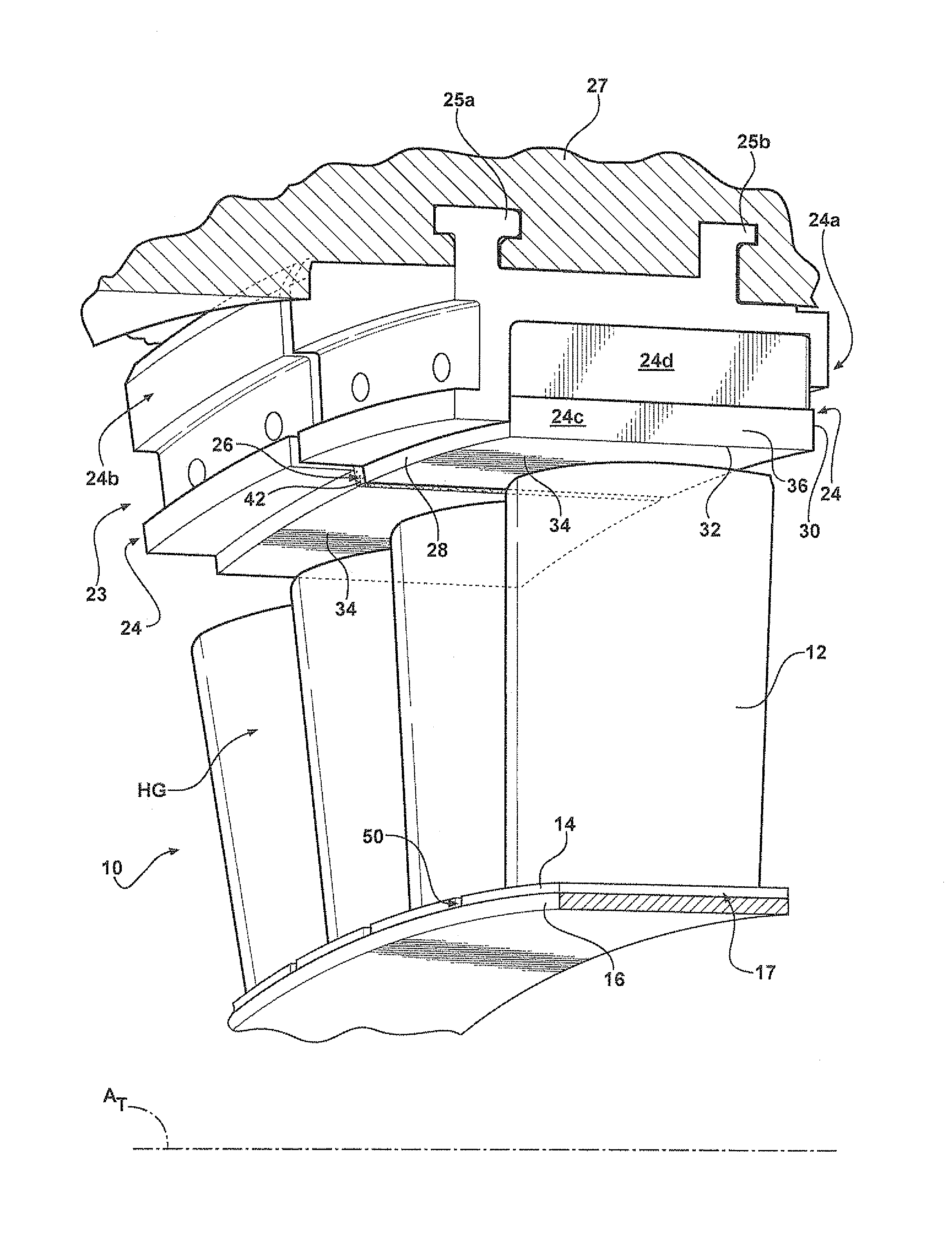
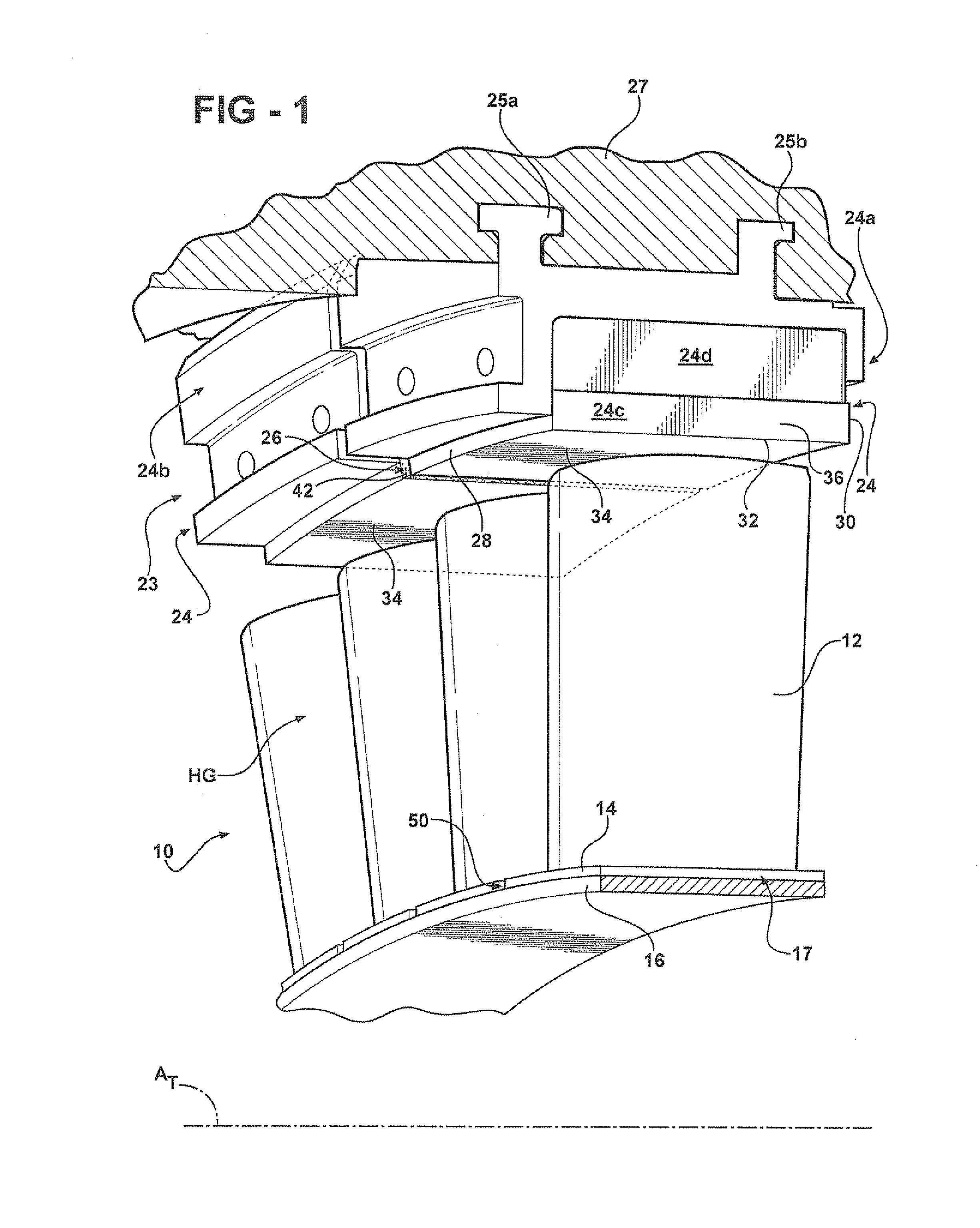
[0021]According to aspects of the present invention, FIG. 1 illustrates a portion of a stage 10 of a turbine engine. The stage 10 is disposed in a hot gas flow path HG of the engine and includes a plurality of rotating components illustrated as blades 12, and a plurality of non-rotating stationary components (not shown), such as vanes, circumferentially disposed about a turbine axis AT.

[0022]Typically, the turbine engine includes a plurality of stages, each including a plurality of blades 12 and a plurality of vanes. Each of the blades 1...


PUM


Abstract

A sealing arrangement for use in a turbine engine having ceramic components. The sealing arrangement is retained in a seal gap formed between adjacent segments and is compliant to accommodate variations in the size of the seal gap as the adjacent segments move relative to one another.

Description

FIELD OF THE INVENTION[0001]The present invention relates generally to a sealing arrangement for use in a turbine engine having ceramic components, and more particularly, to a sealing arrangement that is retained in a gap formed between adjacent segments for limiting passage of gases through the gap.BACKGROUND OF THE INVENTION[0002]In multistage rotary machines used for energy conversion, a fluid is used to produce rotational motion. In a gas turbine engine, for example, a gas is compressed in a compressor and mixed with a fuel source in a combustor. The combination of gas and fuel is then ignited for generating combustion gases that are directed to turbine stage(s) to produce rotational motion.[0003]Typically, a plurality of non-rotating vane components and a plurality of rotating blade components are assembled circumferentially about an axial flow path of the engine. The vane and blade components include shroud segments that are mounted circumferentially about the axial flow path ...

Claims


Application Information

Patent Timeline
IPC IPC(8): F01D11/00
CPCF01D5/284F01D11/006F16J15/3288Y10S416/50F05D2240/11F05D2240/80F16J15/442
Inventor CAMPBELL, CHRISTIAN X.MERRILL, GARY B.
Owner SIEMENS ENERGY INC
Why Eureka
Try Eureka