Electronically monitored injection device

a technology of injection device and electronic monitoring, which is applied in the direction of intravenous device, medical device, medical device, etc., can solve the problems of serious hazards, different unwanted conditions likely to occur during the operation of mechanical injection device, and the mechanical perceptive feedback may be rather limited, so as to reduce the risk of inaccurate or incorrect dose delivery

Active Publication Date: 2011-01-13
NOVO NORDISK AS
View PDF57 Cites 49 Cited by
  • Summary
  • Abstract
  • Description
  • Claims
  • Application Information

AI Technical Summary

Benefits of technology

[0013]Having regard to the problems and deficiencies identified above, it is an object of a first aspect of this invention to reduce the risk of imprecise or...

Problems solved by technology

Several different unwanted conditions is likely to occur during operation of mechanical injection devices, such as the occurrence of a blocked injection needle or the patients usage of an injection device which has not been properly primed or purged prior to making an injection.
Such conditions may present serious hazards if they are not acknowledged by the user and appropriate action is taken.
However, when using spring assisted injection devices, such as the ones shown in WO2008/037801, the mechanical perceptive feedback may be rather limited.
If the needle is withdrawn too soon after the medicament has been injected, there is a risk that at least some of the injected medicament may escape through the needle wo...

Method used


Image

  • Electronically monitored injection device
  • Electronically monitored injection device
  • Electronically monitored injection device

Examples


example 1

[0098]In this example, the dose speed parameter “v” and the dose size “Vol” which has been delivered during dose delivery are used for calculating a recommended needle retracting waiting period. In this example, the single dose speed parameter v is estimated as an average value derived from the dose speed profile. Also, the size of the dose is taken into account. In the example, U100 insulin (having a concentration of 100 International Units per ml) is accommodated in the cartridge and an injection needle of dimension G31 is connected to the injection device.

[0099]The controller of the injection device is provided with a storage having a look-up table pre-loaded into the storage by which combinations of dose sizes and dosing speeds are stored and where appropriate waiting times are stored which correspond to given combinations of dose size and dose speed. For this example, appropriate values of the data in the look-up table can be seen in Table 1.

TABLE 1Dose Speed (IU / sec.)Dose Size...

example 2

[0101]In this example the needle retraction waiting period is calculated by the controller of the injection device by taking into account the Dose speed parameter “v” and the Dose size “Vol” which has been delivered during dose delivery. Again, the dose speed parameter denotes the average dose speed as calculated after completion of the injection operation.

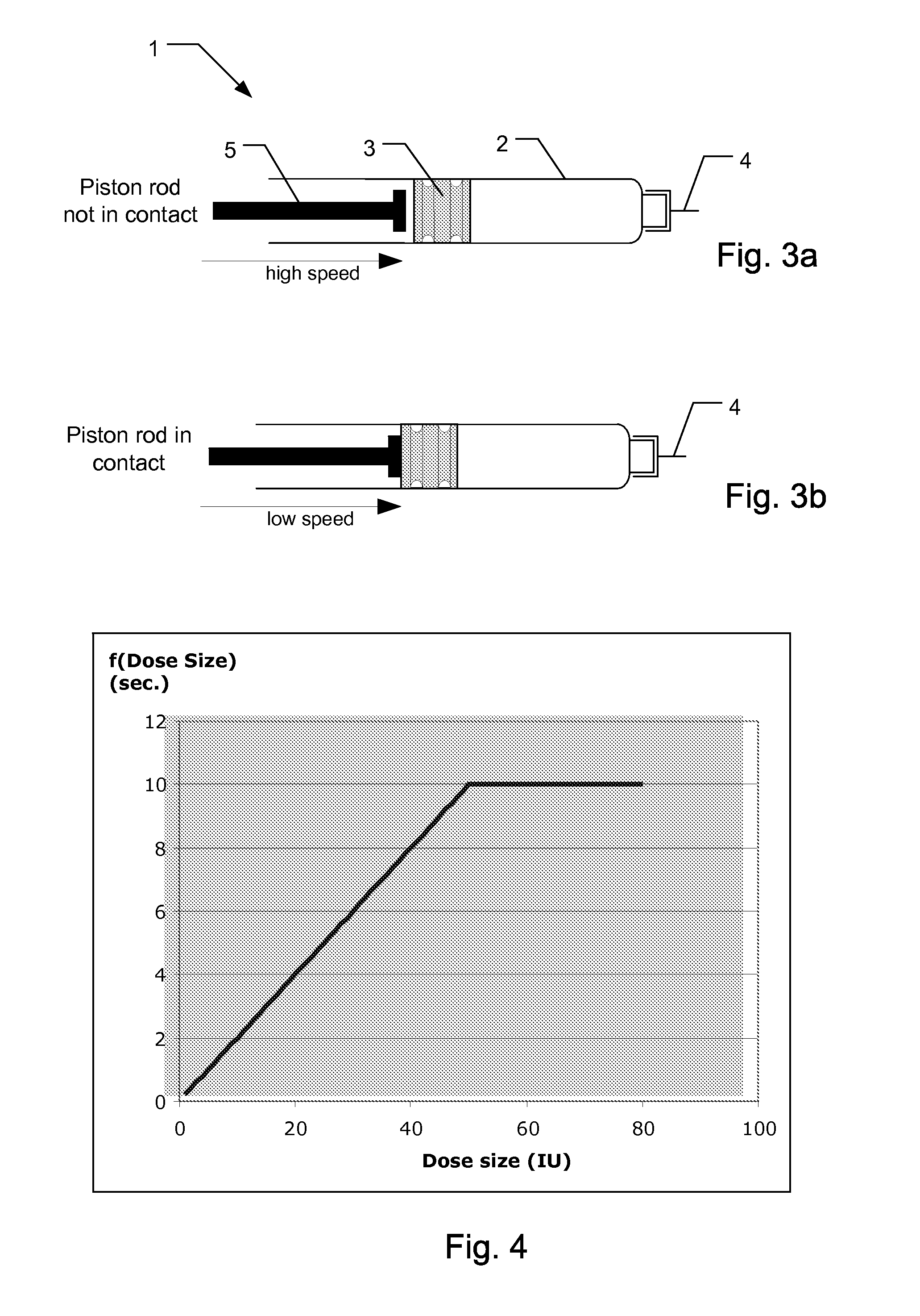
[0102]The recommended waiting time which should elapse after the piston rod has come to a standstill but before the needle can be safely retracted can be calculated using the formula

waiting time=f(Dose size)+g(Dose speed)

where f(Dose size) is a time contribution which takes into account the amount being injected and where g(dose speed) is a time contribution which takes into account the dose speed of the dose that has been injected.

[0103]f(Dose size) may be defined by the function:

f(Dose size)=min (10 s; Vol*0.2 sec. / IU)

[0104]In FIG. 4, the dose size contribution f(Dose size) is shown as a function of varying dose sizes.

[0105]The ...


PUM


Abstract

The present invention relates to a medical injection device (1) for use in combination with a medicament filled cartridge (2), the injection device being provided with a spring-assisted injecting mechanism where energy released from the spring moves a plunger (3) of a held cartridge (2). Sensor circuitry is adapted to detect speed related data during injection so at to detect an abnormal speed condition, such as a needle blocking condition, a priming condition or an air purge condition. The invention also relates to a medical injection device comprising sensor circuitry and user communicating means to provide a recommended needle retraction waiting period which is dependent on the speed of injection.

Description

[0001]The present invention relates to medical injection devices for injecting metered doses of a medicament. More specifically, the invention relates to medical injection devices having means for precisely monitoring dose delivery and means for notifying or alerting a user of the correct or incorrect use of the injection device.[0002]The invention enables a more efficient use of injection devices while offering improvements with respect to dose delivery accuracy.BACKGROUND OF THE INVENTION[0003]In the disclosure of the present invention reference is mostly made to the treatment of diabetes by injection or infusion of insulin, however, this is only a preferred use of the present invention.[0004]In order to permit a patient to administer a proper dose, various mechanical injection devices have been proposed which offer additional electric circuitry for measuring and displaying the size of a dose which will be administered during an injection procedure. Examples of such devices are sh...

Claims


Application Information

Patent Timeline
IPC IPC(8): A61M5/20
CPCA61M5/1452A61M2205/6018A61M5/16804A61M5/1685A61M5/172A61M5/20A61M5/3146A61M5/31525A61M5/31533A61M5/31565A61M5/3157A61M2205/3372A61M2205/3389A61M2205/581A61M2205/582A61M5/1454
Inventor JESPERSEN, SOREN KRAGHGJODESEN, CLAUS URUPLARSEN, ANDRE
Owner NOVO NORDISK AS
Why Eureka
Try Eureka