Modular enclosure

a module and enclosure technology, applied in the field of enclosures, can solve the problems of difficult repair, modification, change or rearrangement of many conventional sheds, and a substantial amount of time, labor, and skill in building and construction of conventional sheds

Inactive Publication Date: 2011-01-20
LIFETIME PRODUCTS
View PDF58 Cites 9 Cited by
  • Summary
  • Abstract
  • Description
  • Claims
  • Application Information

AI Technical Summary

Benefits of technology

[0023]Still another aspect is an enclosure that may include one or more components that may be interconnected to form a structure. The structure may include walls, roof, floor, etc. and these components can be connected. Preferably, the components can be relatively quickly and easily connected and disconnected. Advantageously, this may allow the components to be easily reconfigured, repaired and / or replaced. In addition, this may allow the structure to be easily moved, reused and the like.
[0050]Still another aspect is a panel constructed from blow-molded plastic that may include a first side; a second side that is generally spaced apart from the first side by a distance; a hollow interior portion disposed between the first side and the second side, the hollow interior portion formed during the blow-molding process; a first pattern disposed on the first side of the panel, at least a portion of the first pattern extending towards the second side; a second pattern disposed on the second side of the panel, at least a portion of the second pattern extending towards the first side; at least one position of intersection generally disposed where the first pattern and the second pattern overlie, the first pattern and the second pattern being spaced apart by a distance at the position of intersection that is less than the distance separating the first side and the second side; and at least one first depression disposed at the position of intersection that extends from the first side towards the second side, the at least one first depression having a length that is less than the distance separating the first side and the second side, the at least one first depression being sized and configured to increase the strength of the panel.

Problems solved by technology

Disadvantageously, conventional sheds often require a substantial amount of time, labor, skill and effort to build and construct.
The windows and vents of many conventional sheds, however, often require a number of interconnected components and are difficult to manufacture and install.
Additionally, many conventional sheds are difficult to repair, modify, change or rearrange because the sheds may be difficult or impossible to disassemble or dismantle.
Accordingly, it is often impractical or unfeasible to move or reconfigure many conventional sheds.
Wooden sheds, however, are relatively heavy and require a large amount of time to construct and assemble.
These numerous parts typically increase the costs of the shed and require a large amount of time and effort to construct the shed.
In addition, wooden sheds typically deteriorate over time and often require continual maintenance.
For example, conventional wooden sheds may be damaged by rotting or otherwise deteriorating when exposed to the elements.
In addition, the wood may warp or decay over time.
Undesirably, this may result in significant maintenance costs.
Disadvantageously, the sheet metal is often flexible and easily damaged.
In particular, the sheet metal walls may be damaged by forces being applied to either the inner or outer walls of the shed.
In particular, this may cause the walls to undesirably bow inwardly or outwardly and, in some circumstances, may create an opening in the wall.
Significantly, the damaged sheet metal may be more susceptible to rust or corrosion and the damaged sheet metal may be very difficult to repair or replace.
In addition, conventional metal sheds often require a plurality of screws or bolts to assemble the shed, which may increase manufacturing costs and the time required to assemble the shed.
Moreover, metal sheds often have a tendency to rust and deteriorate over time, especially when exposed to the elements.
Thus, metal sheds may have to be painted or otherwise protected from rusting or oxidation.
The materials used to construct conventional sheds are often heavy and bulky.
Accordingly, many of the components are large and bulky.
In addition, if these components are constructed from wood or metal, then the components may be very heavy.
Thus, the components of conventional sheds may be large, awkward, heavy and generally unwieldy.
Many conventional sheds are shipped in an unassembled configuration because of their large size in the assembled configuration.
The weight of the components, however, may result in significant shipping expenses and those expenses may be compounded every time the shed is transported or shipped.
For example, there may be significant costs when the manufacturer ships the shed to the retailer, which the consumer may ultimately have to pay.
Many consumers may have to pay more to have the shed delivered from the retailer because of the weight of the packaging.
In addition, many consumers may be unwilling or unable to purchase these conventional sheds because they have no practical way of taking the shed home.
Specifically, many consumers are unable to lift or move the packaging of many conventional sheds.
In particular, the consumer may also have to rent or borrow a forklift to load and unload the shed from the vehicle.
Accordingly, these large costs and difficulties in transportation may discourage many potential consumers from purchasing conventional sheds.
In addition to conventional sheds being constructed from heavy and bulky materials and components, conventional sheds are often shipped in very large and heavy boxes.
These gigantic shipping boxes often will not fit in a typical retail consumer's vehicle.
Accordingly, the size and weight of many known sheds is substantial, which may greatly complicate and increase the costs of shipping.

Method used


Image

  • Modular enclosure
  • Modular enclosure
  • Modular enclosure

Examples


Embodiment Construction

[0101]Before describing preferred and other exemplary embodiments in greater detail, several introductory comments regarding the general applicability and scope of the invention may be helpful.

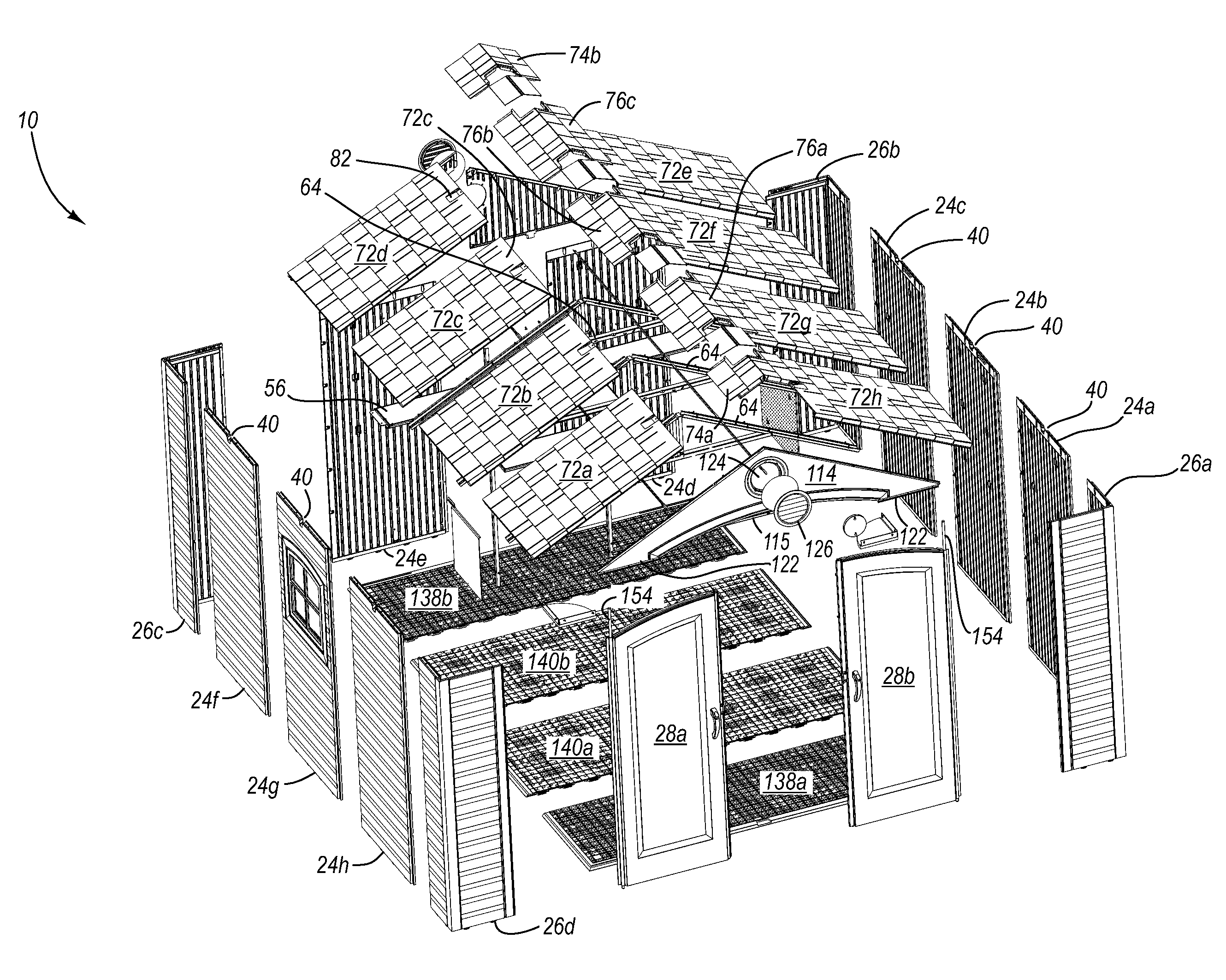
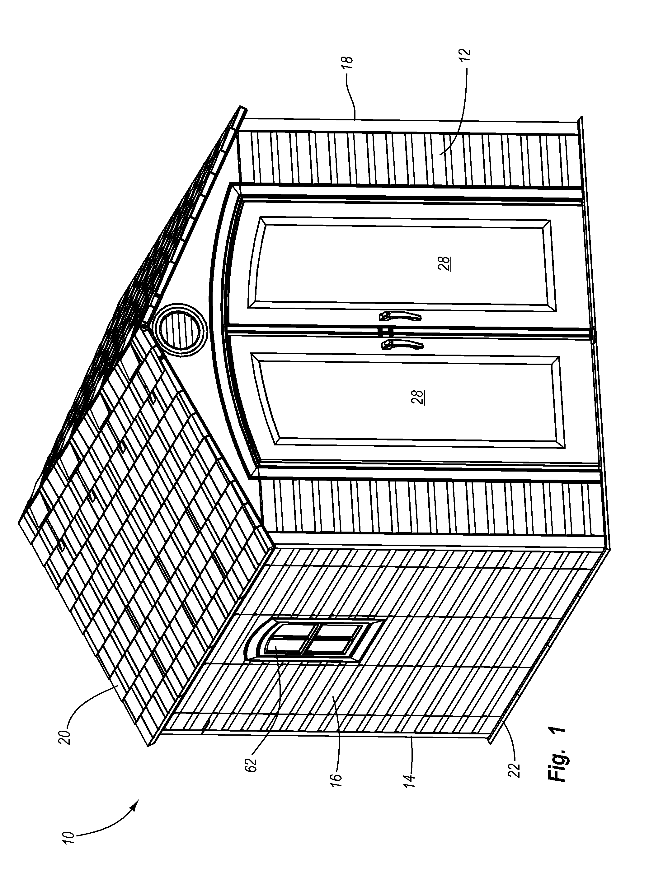
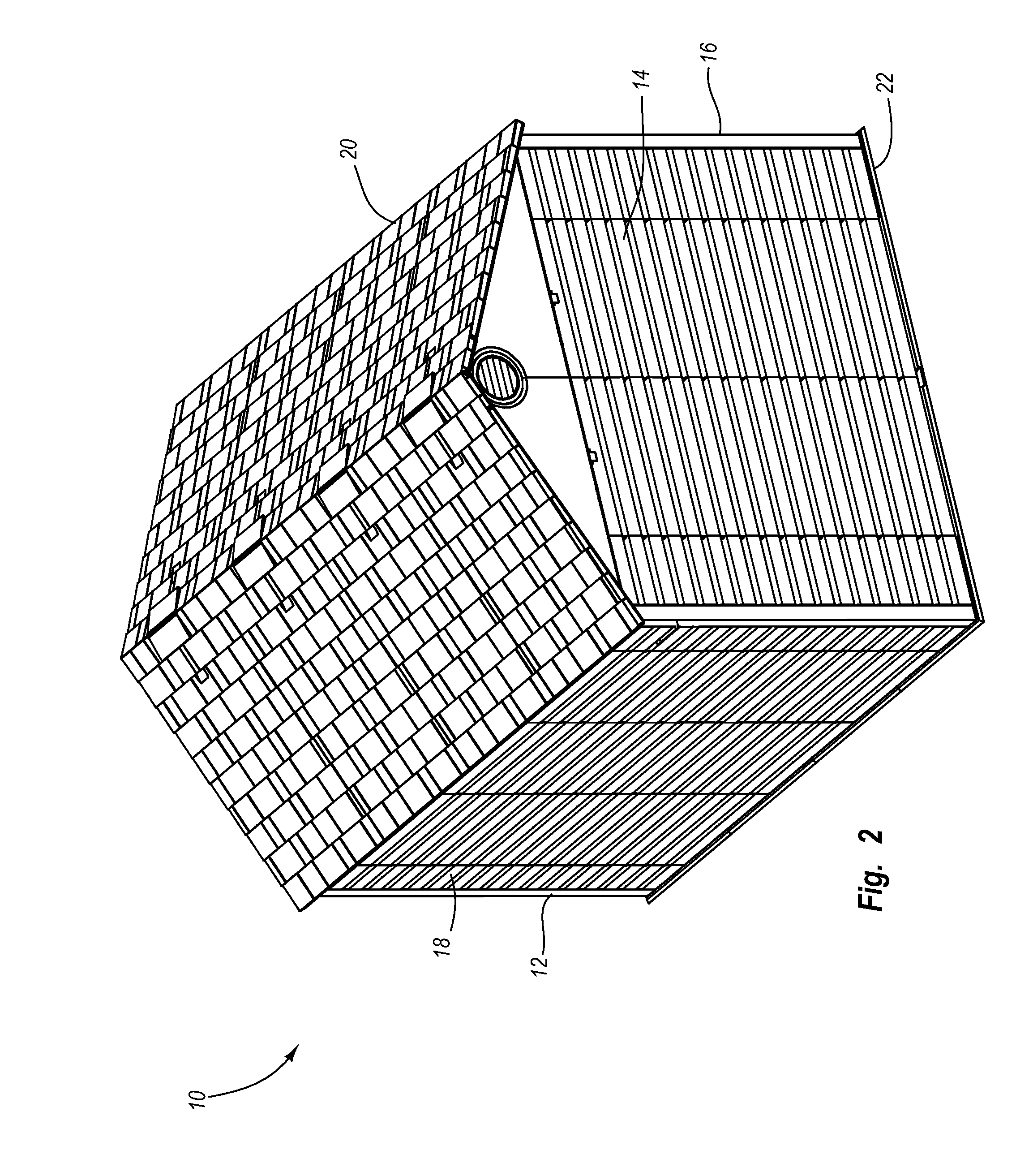
[0102]First, the following detailed description of preferred and other exemplary embodiments is generally directed towards an enclosure such as a storage enclosure. It will be appreciated that the storage enclosure may be used to temporarily and / or permanently store a variety of items, objects, devices and the like depending, for example, upon the intended use of the enclosure. The principles of the present invention, however, are not limited to storage enclosures. It will be understood that, in light of the present disclosure, the enclosures disclosed herein can have a variety of suitable shapes, arrangements, configurations and the like; and that the enclosures can be used for a variety of different functions, purposes and uses.

[0103]Second, the enclosures discussed in more detail below and ...


PUM

PropertyMeasurementUnit
widthaaaaaaaaaa
widthaaaaaaaaaa
lengthaaaaaaaaaa

Abstract

A modular enclosure may include a number of interlocking components, such as panels, that may be interconnected to form sidewalls, roof and / or floor. The panels may be constructed from blow-molded plastic and a first pattern may be disposed on one surface and a second pattern may be disposed on an opposing surface. One or more points of intersection may be located where the first pattern and the second pattern overlie, and a depression may be disposed at the points of intersection. The depressions are preferably sized and configured to increase the strength and / or rigidity of the panel.

Description

CROSS-REFERENCE TO RELATED APPLICATIONS[0001]This application is a continuation of U.S. patent application Ser. No. 11 / 091,848, filed on Mar. 28, 2005, now U.S. Pat. No. 7,797,885, which is incorporated by reference in its entirety.[0002]U.S. patent application Ser. No. 11 / 091,848, filed on Mar. 28, 2005, now U.S. Pat. No. 7,797,885, is a continuation-in-part of U.S. patent application Ser. No. 10 / 890,601, filed on Jul. 14, 2004, now U.S. Pat. No. 7,210,277.[0003]U.S. patent application Ser. No. 11 / 091,848, filed on Mar. 28, 2005, now U.S. Pat. No. 7,797,885, claims priority to and the benefit of U.S. provisional patent application Ser. No. 60 / 586,387, entitled Shed Constructed from Blow-molded Plastic, filed on Jul. 8, 2004, now expired. U.S. patent application Ser. No. 11 / 091,848, filed on Mar. 28, 2005, now U.S. Pat. No. 7,797,885, claims priority to and the benefit of U.S. provisional patent application Ser. No. 60 / 557,369, entitled Shed Constructed from Blow-molded Plastic, fil...

Claims


Application Information

Patent Timeline
Patent Type & Authority Applications(United States)
IPC IPC(8): E04H1/12E04C2/20A47B13/08E04B1/343E04B1/346E04B7/02E04B7/16E04B7/20E04C2/00E04C2/54E04D3/35E04D3/40E04F13/00E04F15/00E04F19/00E04H1/00E06B5/02H01B17/32H01B17/60
CPCE04B1/34321E04B7/022E04B7/20E06B5/02E04D3/357E04D3/40E04H1/1205E04B2001/34389E04B1/34317
Inventor MOWER, BARRY D.STEED, BRENTCALKIN, JAYWATSON, NEILASTLE, ROBERT A.STRONG, L. CURTISHOWE, RICHWINTER, DAVID C.ASHBY, KENT
Owner LIFETIME PRODUCTS
Why Eureka
Try Eureka