
Image forming apparatus

a technology of forming apparatus and forming surface, which is applied in the direction of electrographic process apparatus, coating, instruments, etc., can solve the problems of deteriorating the definition of image, complex configuration, and uneven coating level

Inactive Publication Date: 2011-01-20
S PRINTING SOLUTION CO LTD
View PDF5 Cites 7 Cited by
  • Summary
  • Abstract
  • Description
  • Claims
  • Application Information

AI Technical Summary

Benefits of technology

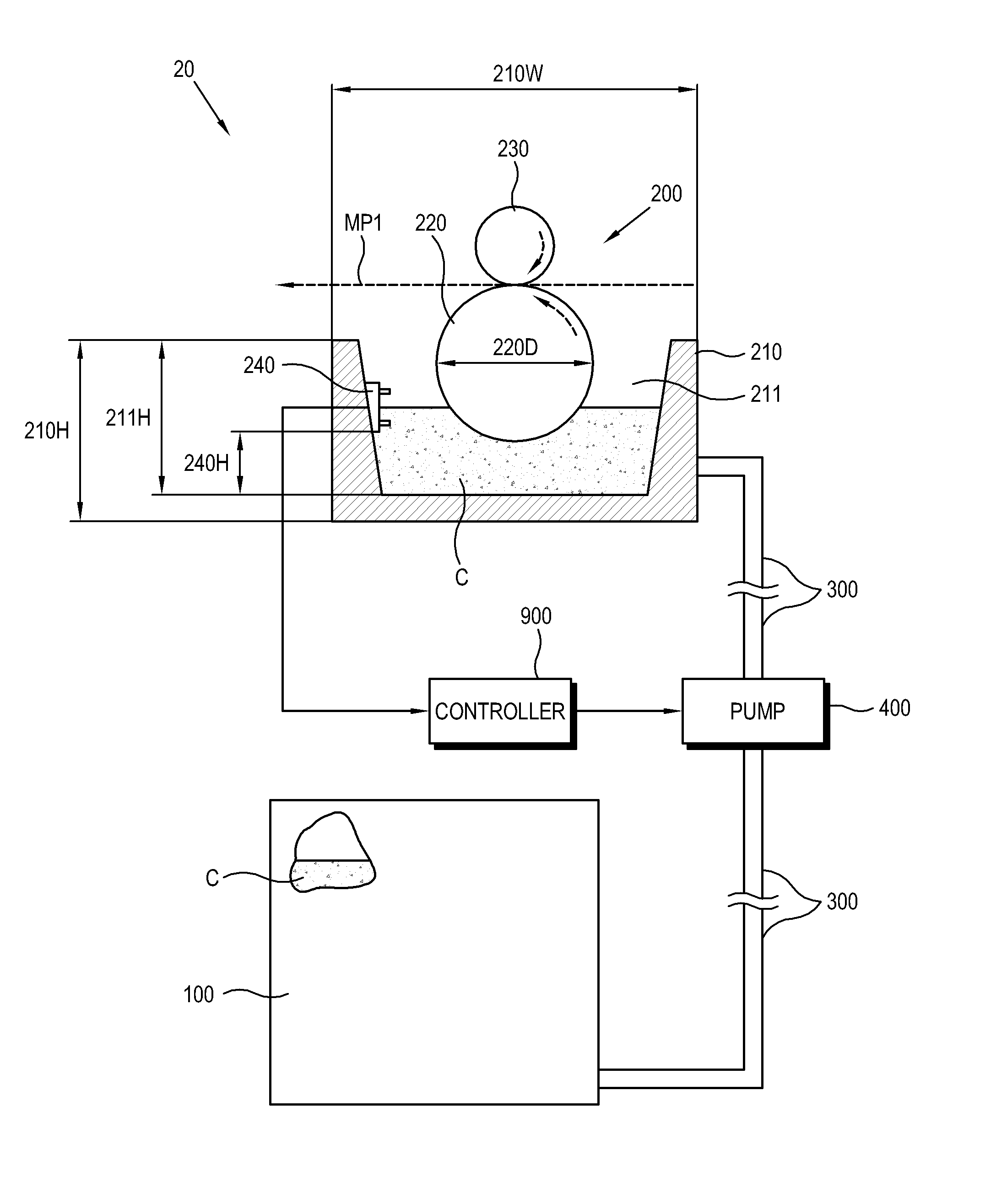
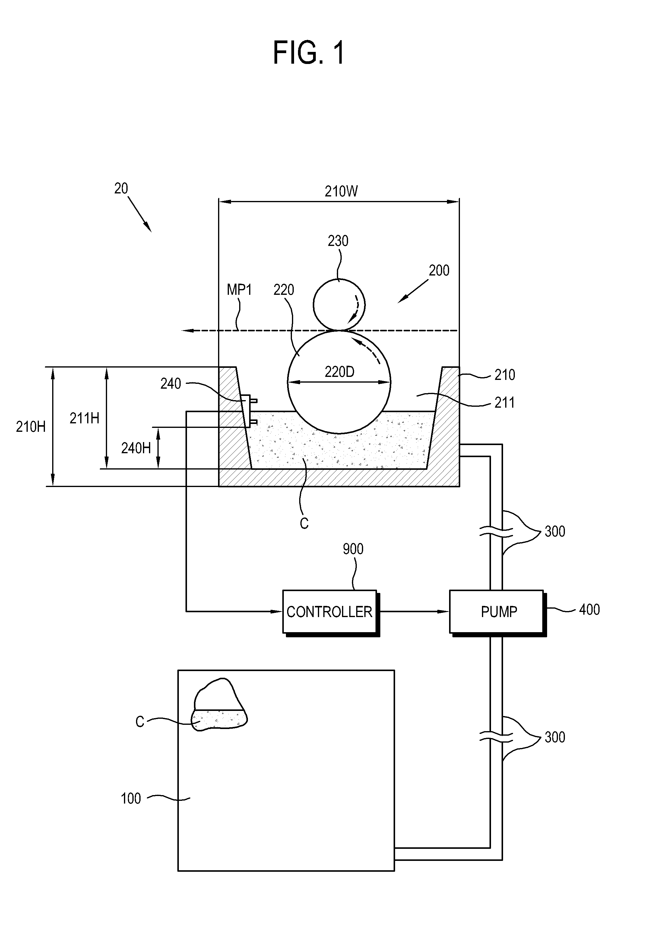
[0013]Embodiments of the present general inventive concept provide an image forming apparatus capable of applying a uniform coating level to a print medium even though a rotating speed of a coating roller changes.

Problems solved by technology

In an inkjet image forming apparatus, the ink jetted to the print medium and forming an image permeates into the print medium since it is liquid, thereby deteriorating the definition of the image.
Further, the configuration becomes complicated since the channels are needed corresponding to the supply and the recovery, respectively.
Thus, a coating level may not be uniform but varied depending on the print medium.
Additionally, the conventional image forming apparatus has a problem that the coating is usable with the print media loaded onto the existing loading tray.
Thus, when a special print medium having no need of the coating is loaded onto the loading tray, unnecessary coating is performed, thus lowering the quality of a formed image.
However, this method causes the image forming apparatus to have a complicated configuration and is inconvenient for a user.

Method used


Image

  • Image forming apparatus
  • Image forming apparatus
  • Image forming apparatus

Examples


Embodiment Construction

[0046]Hereinafter, exemplary embodiments of the present inventive general concept will be described in detail with reference to accompanying drawings. First, the following description principles are applied to all exemplary embodiments to be described below. If one embodiment has the same element as a previous embodiment, description about this element may be omitted. Also, if elements are similar to each other with respect to their function or structure but different from each other, reference numerals may be given thereto differently according to exemplary embodiments or drawings. Further, the drawing may mainly show elements directly related to a corresponding exemplary embodiment and omit the other elements, but these elements are not practically excluded in realizing the present general inventive concept.

[0047]Reference will now be made in detail to the exemplary embodiments of the present general inventive concept, examples of which are illustrated in the accompanying drawings...


PUM


Abstract

An image forming apparatus including a medium feeding unit to supply a print medium, a medium coating assembly to coat the print medium with a coating liquid, and an image forming unit to form an image on the coated print medium, the medium coating assembly including a container to store the coating liquid, a coating unit to coat the print medium with the coating liquid, a channel to guide the coating liquid to move between the container and the coating unit, and a controller to selectively control the coating liquid to be supplied from the container to the coating unit and to be recovered from the coating unit to the container through the same channel.

Description

CROSS-REFERENCE TO RELATED APPLICATIONS[0001]This application claims priority under 35 U.S.C. §119(a) from Korean Patent Application No. 10-2009-0063901, filed on Jul. 14, 2009 in the Korean Intellectual Property Office, the disclosure of which is incorporated herein by reference.BACKGROUND[0002]1. Field of the Invention[0003]The present general inventive concept relates to an image forming apparatus forming an image on a print medium, and more particularly, to an image forming apparatus having a structure of coating on a print medium in a stage previous to forming an image.[0004]2. Description of the Related Art[0005]An image forming apparatus employs various methods for forming an image on a print medium. For example, there are laser-printer type methods for forming a visual image with a developer on a photosensitive body having an electrostatic latent image and transferring it to a print medium, inkjet type methods of jetting ink on the print medium, etc.[0006]In an inkjet image ...

Claims


Application Information

Patent Timeline
IPC IPC(8): B05C9/12B05C1/08
CPCG03G2215/00662B41J11/0015G03G15/00G03G15/06
Inventor MUN, IL-JUYOUN, KARP-SIKHA, DONG-WOOLEE, IN-SUKIM, YOUNG-CHOON
Owner S PRINTING SOLUTION CO LTD
Learn More