Shielding tape with edge indicator

a technology of shielding tape and indicator, which is applied in the direction of insulated conductors, power cables, cables, etc., can solve the problems of time-consuming and difficult positioning of the outer edge of the overlap

Inactive Publication Date: 2011-01-20
PCT INT
View PDF62 Cites 16 Cited by
  • Summary
  • Abstract
  • Description
  • Claims
  • Application Information

AI Technical Summary

Benefits of technology

[0005]The present invention also includes a cable having a center conductor and an outer shielding tape as described above that surrounds the center conductor. The shielding tape may surround the conductor directly (i.e., there are no intervening structures between the conductor and the tape) or indirectly (i.e., there are one or more

Problems solved by technology

Conventional shielding tape, however, is of uniform color, making t

Method used


Image

  • Shielding tape with edge indicator
  • Shielding tape with edge indicator

Examples


Embodiment Construction

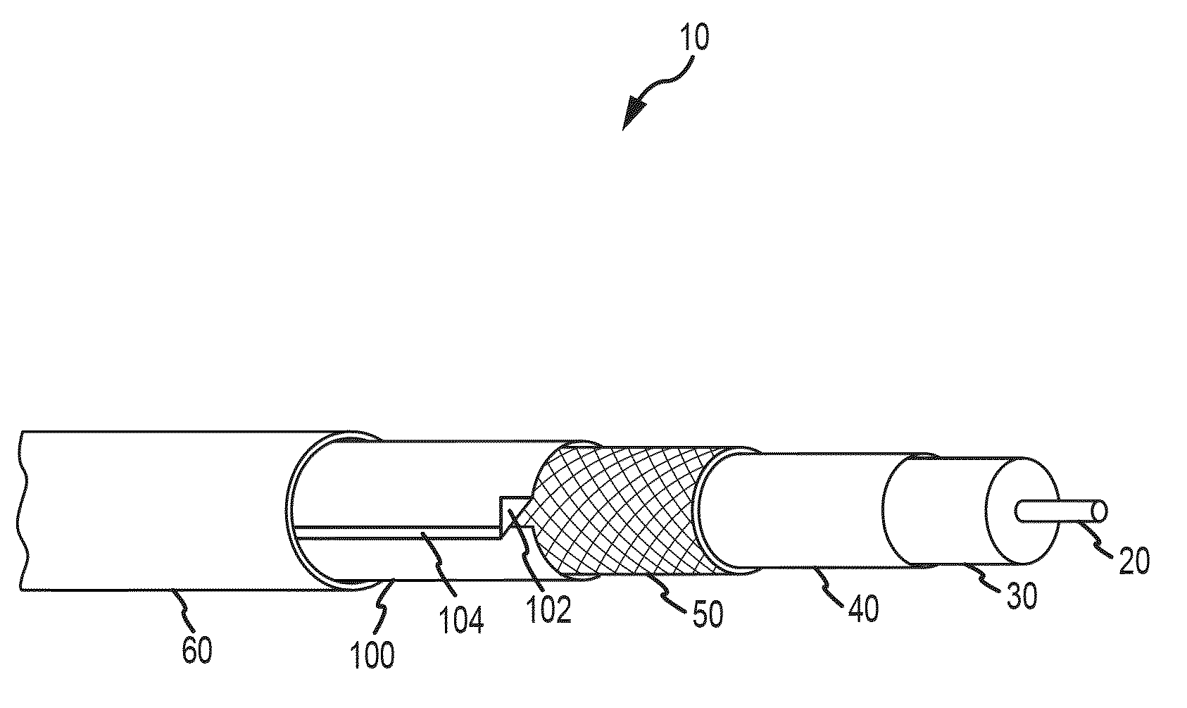
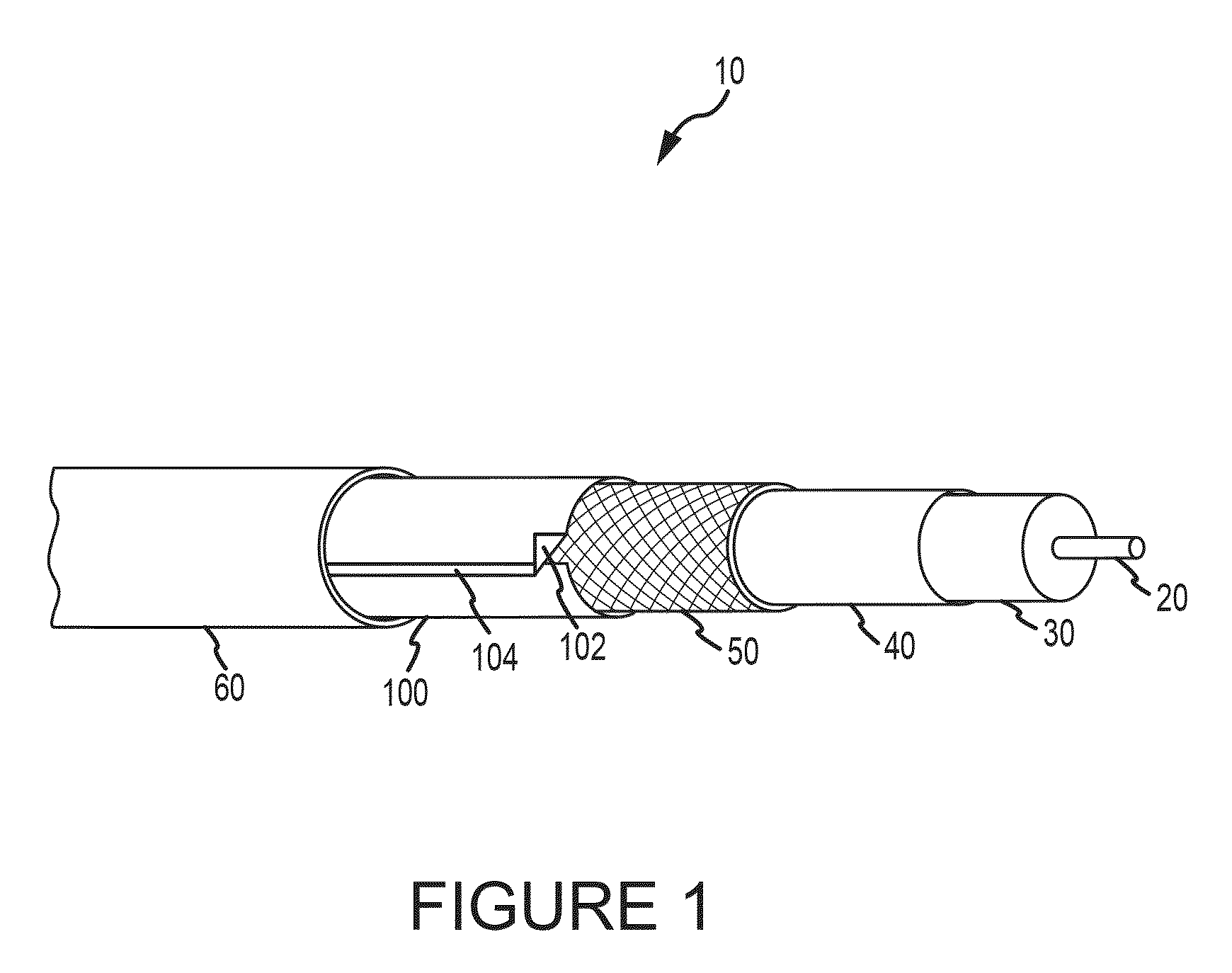
[0007]Turning now to the Figures, where the purpose is to describe a preferred embodiment of the invention and not to limit same, FIG. 1 shows a coaxial cable 10 that includes a shielding tape 100 according to the invention. Cable 10 includes a center conductor 20, a dielectric 30, an inner foil 40, a braid material 50, an outer foil 100, and an outer jacket 60.

[0008]The shielding tape 100 (also referred to herein as “outer foil”) is wrapped about the longitudinal axis of the cable 10 with the inner edge (not shown) of shielding tape 100 in direct contact with the braid 50, and the outer edge 102 (denoted by the label “overlap” in FIG. 1) overlapping the inner edge. The outer edge 102 includes an indicator 104 that identifies edge 102 of the shielding tape 100 (the indicator is also referred to in FIG. 1 as the “stripe”). Both edges of the shielding tape 100 may include an indicator 104 so that shielding tape 100 is not handed when used.

[0009]The indicator may be visual, tactile, or...


PUM


Abstract

The present invention comprises a shielding tape comprising at least one shielding layer, at least one separator layer, a first (inner) edge, and a second (outer) edge. The shielding tape further includes an indicator extending along at least a portion of the outer edge. The indicator is for identifying the outer edge when the outer edge overlaps the inner edge when the shielding tape is positioned onto a cable. Alternatively, both edges may have an indicator. The present invention makes it easy to locate the outer edge of the shielding tape for an installer wishing to remove at least some of the shielding tape before crimping or compressing a connector onto the end of a cable.

Description

CROSS REFERENCE TO RELATED APPLICATIONS[0001]This nonprovisional utility application claims priority to U.S. Provisional Patent Application No. 61 / 226,249, filed Jul. 16, 2009 titled “Shielding Tape With Edge Indicator,” the disclosure of which is fully incorporated herein by reference for all purposes.BACKGROUND[0002]Shielding is used a variety of cables to reduce electrical interference that could affect a signal travelling through the cable. The shielding also helps prevent the signal from radiating from the cable and interfering with other devices. One such type of shielding includes a layer of aluminum or other shielding material (such as silver or copper) laminated on a separating layer, such as a plastic, e.g., polyethylene terephthalate (“PET”) or polypropylene (“PP”). This type of shielding, which combines layers of shielding material and separating layers, is often referred to as either “foil,”“laminated tape,”“shielding tape,”“shielding laminate tape,” and combinations or...

Claims


Application Information

Patent Timeline
IPC IPC(8): H05K9/00H01B9/02
CPCH01B7/366H01B11/1813H01B11/1016
Inventor GEMME, PAULVISSER, LEONARD
Owner PCT INT
Why Eureka
Try Eureka