Yield Improvement for Josephson Junction Test Device Formation

a test device and junction technology, applied in the direction of dielectric property measurement, instruments, nuclear elements, etc., can solve the problem of time-consuming and cryogenic temperatures

Active Publication Date: 2011-01-20
RAYTHEON BBN TECH CORP +1
View PDF8 Cites 21 Cited by
  • Summary
  • Abstract
  • Description
  • Claims
  • Application Information

AI Technical Summary

Benefits of technology

[0003]In one aspect of the present invention, an apparatus for measuring component performance includes a feed line having an input port and an output port, a first resonator connected to the feed line, and a first Josephson junction device connected to the first resonator and to ground.
[0004]In another aspect of the present invention, a method for measuring the performanc

Problems solved by technology

The Josephson junction devices operate at cryogeni

Method used


Image

  • Yield Improvement for Josephson Junction Test Device Formation
  • Yield Improvement for Josephson Junction Test Device Formation
  • Yield Improvement for Josephson Junction Test Device Formation

Examples


Embodiment Construction

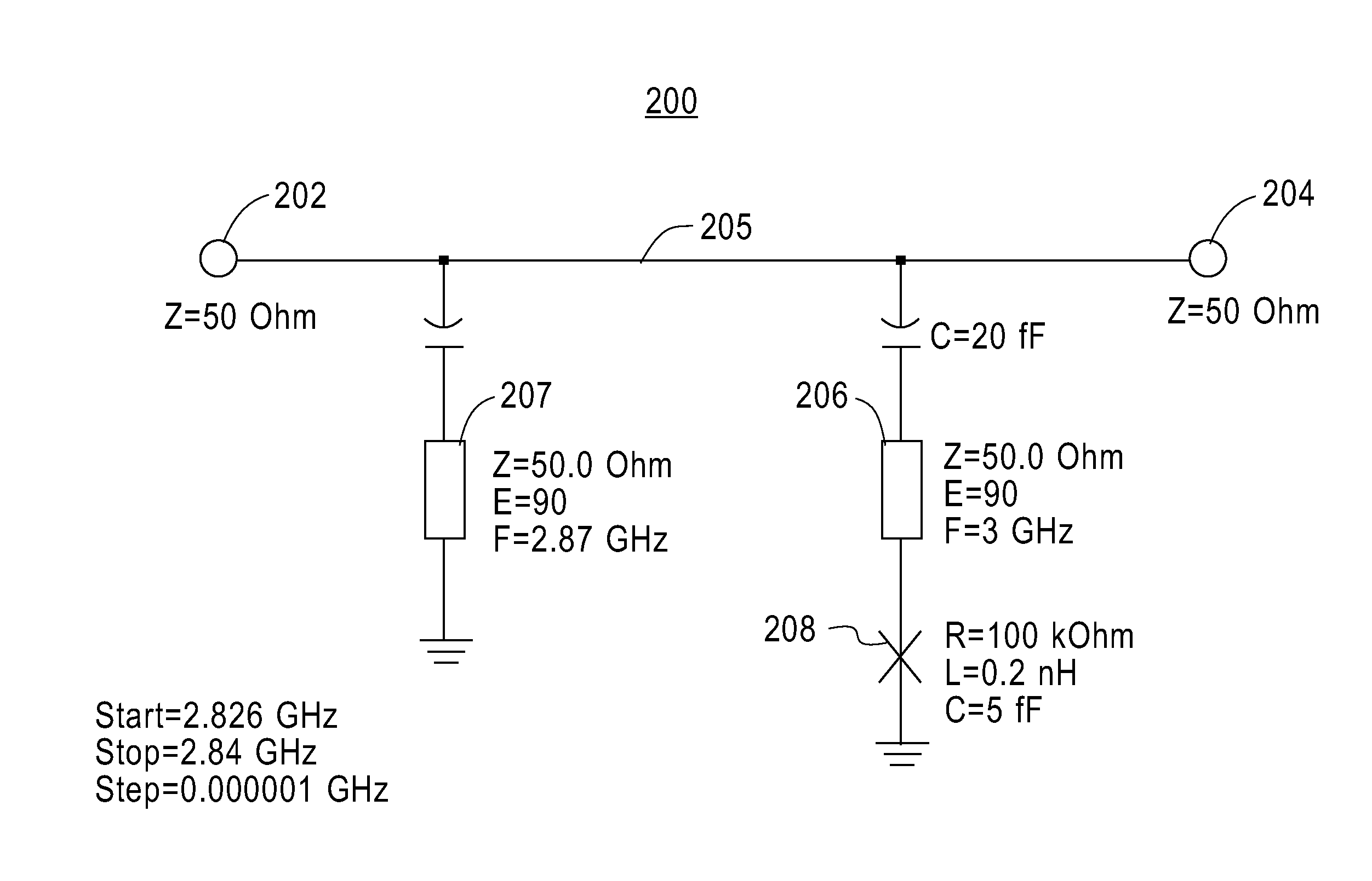
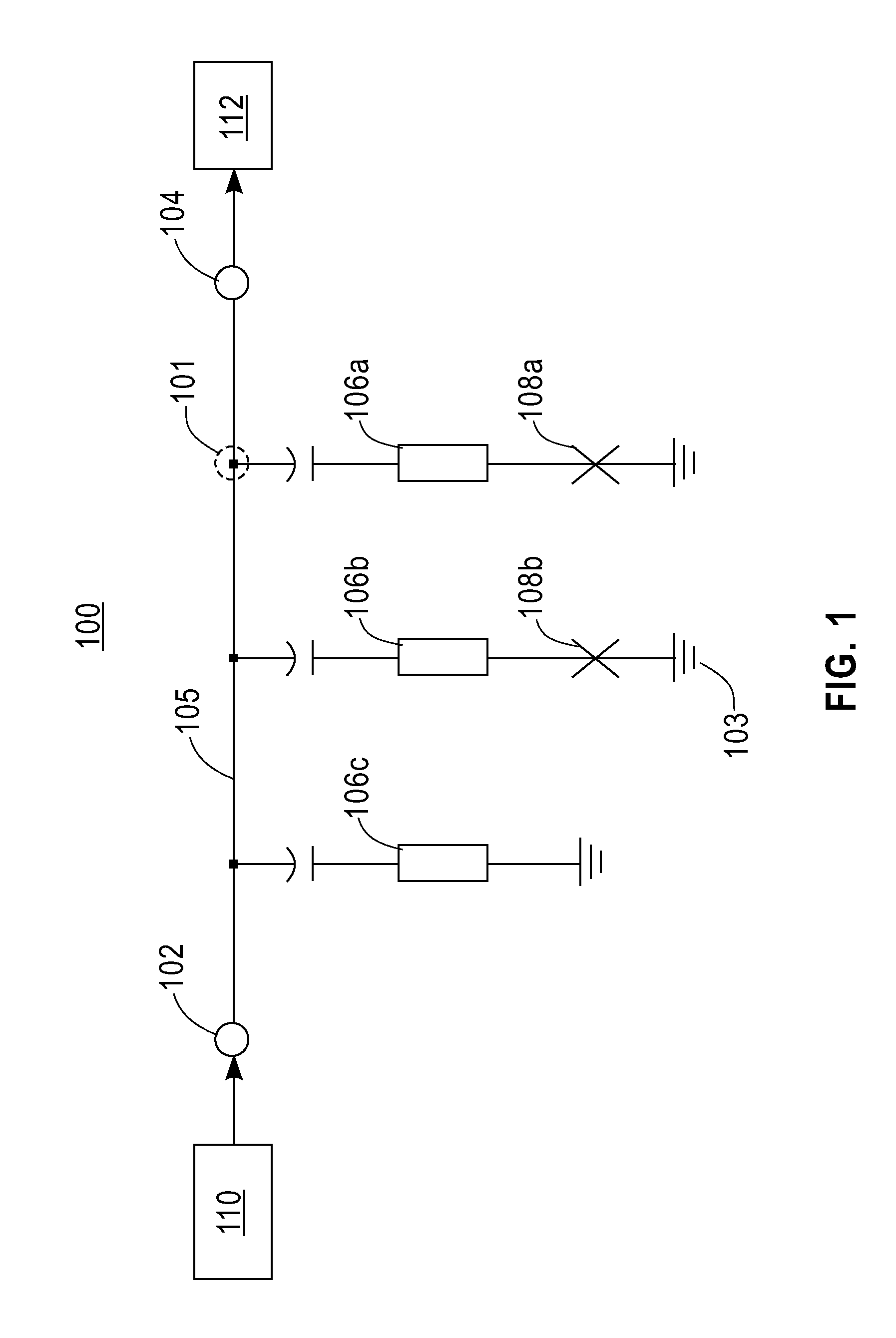
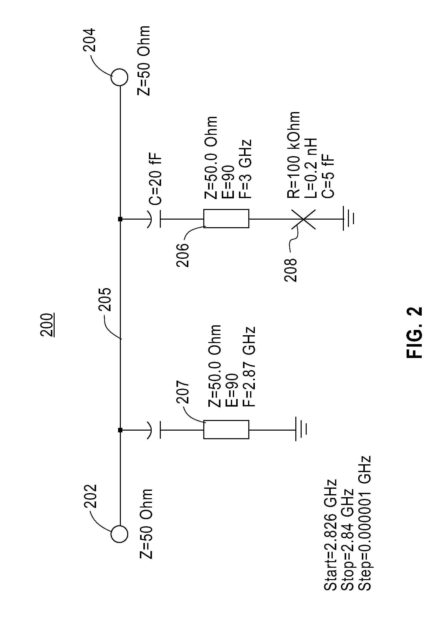
[0010]FIG. 1 illustrates an exemplary embodiment of a system for evaluating Josephson junction devices. The system includes a circuit 100. The circuit 100 includes a feed line 105, an input port 102, and an output port 104. The input port 102 is connected to a microwave emitting device 110, such as, for example, a microwave frequency synthesizer or a network analyzer that is capable of emitting a range of microwave frequencies that excite the circuit 100. The output port 104 is connected to a microwave measuring device 112 that may include, for example, a network analyzer or a homodyne detection circuit that operates to measure the response of the circuit. A first resonator 106a is capacitively coupled to the feed line 105 at a first node 101. The first resonator 106a is also connected to a first Josephson junction device 108a that is, in turn, connected to the second node 103 (ground). The illustrated embodiment further shows a second resonator 106b and Josephson junction device 10...


PUM


Abstract

An apparatus for measuring component performance including a feed line having an input port and an output port, a first resonator connected to the feed line, and a first Josephson junction device connected to the first resonator and to ground.

Description

FIELD OF INVENTION[0001]The present invention relates to Josephson junction devices and superconducting resonators, and more specifically, to testing Josephson junction devices.DESCRIPTION OF RELEVANT ART[0002]Josephson junction devices are superconducting devices that may be used in quantum information systems. The development of superconducting quantum information systems often includes the testing of numerous Josephson junction devices and devices made from Josephson junction devices to gather performance data. The Josephson junction devices operate at cryogenic temperatures that are time consuming to achieve. A system and method that allows multiple Josephson junction devices and devices made from Josephson junction devices to be tested efficiently in a testing cycle is desired.BRIEF SUMMARY[0003]In one aspect of the present invention, an apparatus for measuring component performance includes a feed line having an input port and an output port, a first resonator connected to the...

Claims


Application Information

Patent Timeline
IPC IPC(8): G01R27/04G21C17/00
CPCG01R31/2637G01R27/2688
Inventor KETCHEN, MARK B.KUMAR, SHWETANKSTEFFEN, MATTHIAS
Owner RAYTHEON BBN TECH CORP
Why Eureka
Try Eureka