
Shake correction apparatus, image pickup apparatus, and method for controlling shake correction apparatus

a shake correction and shake technology, applied in the field image pickup apparatus, and control of shake correction apparatus, can solve the problems of optical performance greatly reduced, etc., and achieve the effect of suppressing optical performance reduction

Active Publication Date: 2011-01-20
CANON KK
View PDF6 Cites 5 Cited by
  • Summary
  • Abstract
  • Description
  • Claims
  • Application Information

AI Technical Summary

Benefits of technology

The present invention was made in view of these circumstances, and provides technology that suppresses a reduction in optical performance when correcting optical axis shift.
With the above configuration, according to the present invention, it is possible to suppress a reduction in optical performance when correcting optical axis shift.

Problems solved by technology

However, in Japanese Patent Laid-Open No. 2006-191181, a reduction in optical performance is not considered, so there is a possibility that when a large optical axis shift is corrected, optical performance will be greatly reduced.

Method used


Image

  • Shake correction apparatus, image pickup apparatus, and method for controlling shake correction apparatus
  • Shake correction apparatus, image pickup apparatus, and method for controlling shake correction apparatus
  • Shake correction apparatus, image pickup apparatus, and method for controlling shake correction apparatus

Examples


first embodiment

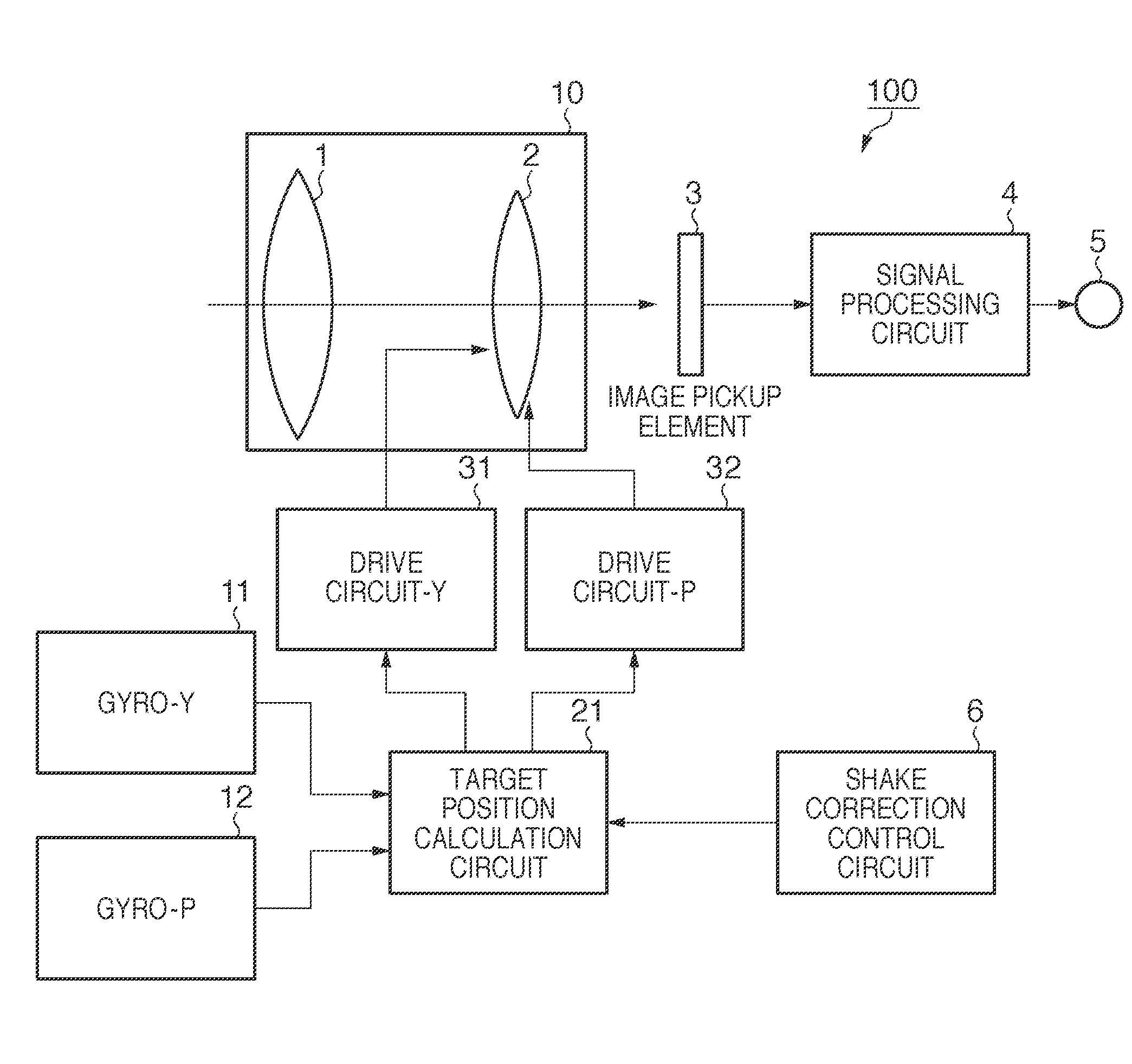
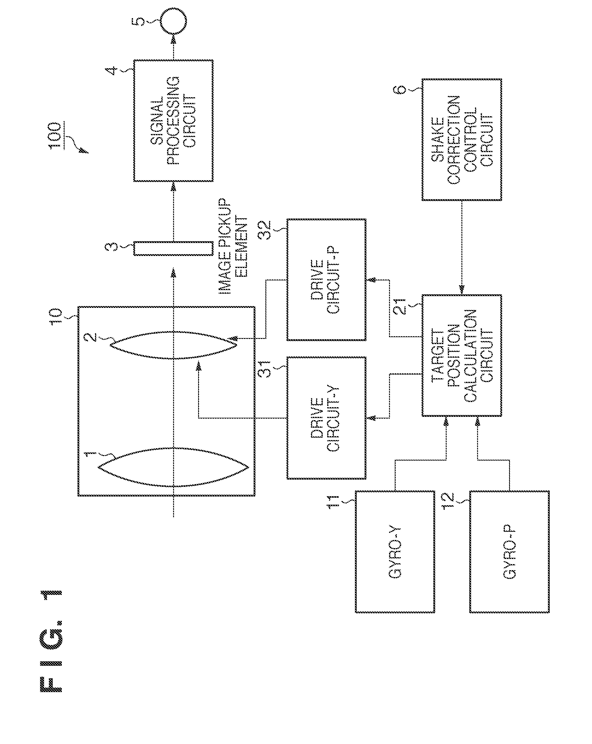
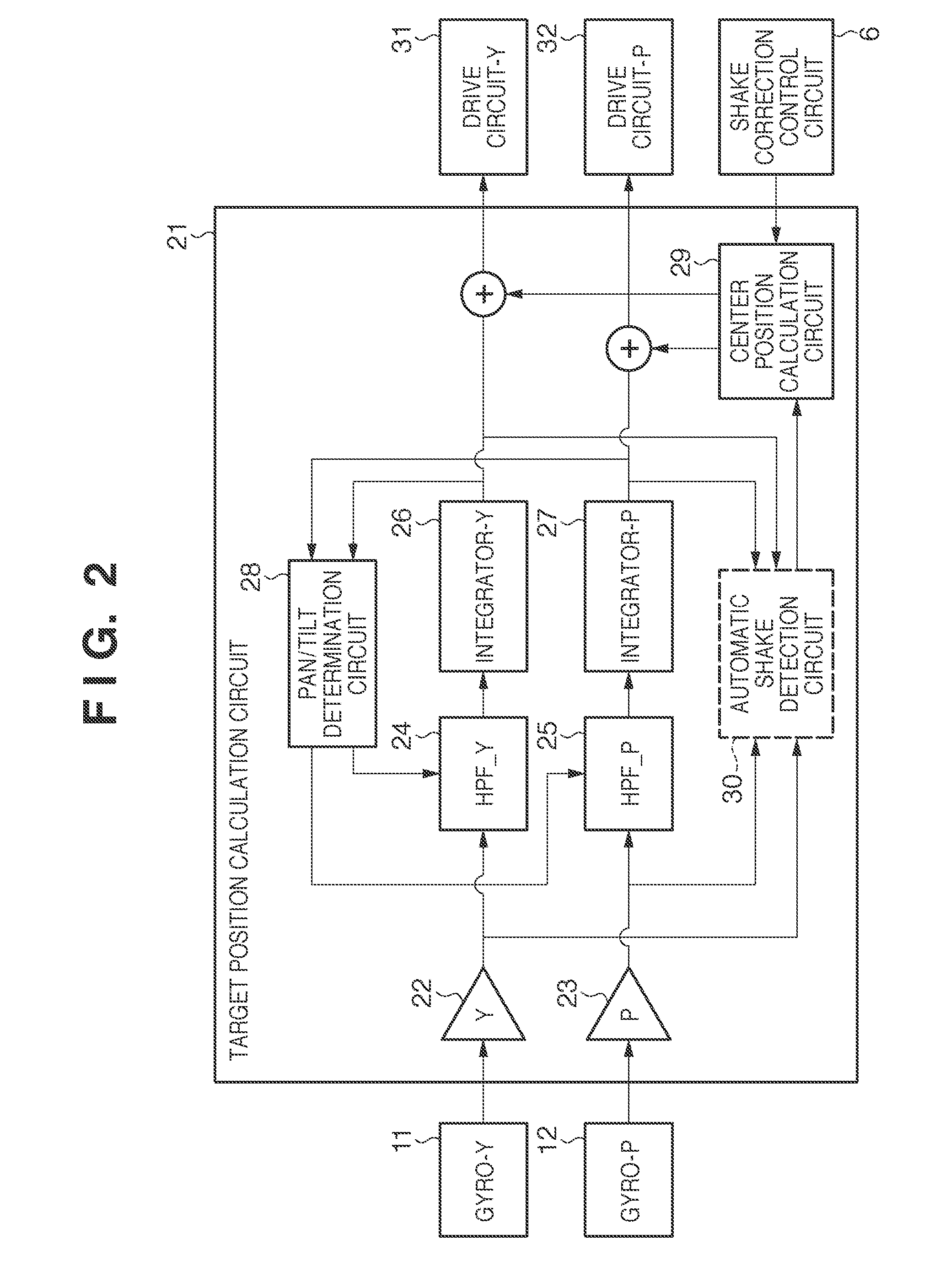
FIG. 1 is a block diagram that shows the configuration of an image pickup apparatus 100 provided with a shake correction apparatus according to the present invention. In FIG. 1, an image pickup optical system 10 includes an image pickup lens 1, and a correction lens 2 for correcting shake applied to the image pickup apparatus 100. The correction lens 2 is capable of moving in a direction orthogonal to the optical axis of the image pickup optical system 10. An image pickup element 3 performs photoelectric conversion of incident light from the image pickup optical system 10. A signal processing circuit 4 processes an electrical signal obtained by the photoelectric conversion in the image pickup element 3, thus converting the electrical signal to a standard video signal or the like, for example. An output terminal 5 outputs the standard video signal obtained from the signal processing circuit 4. By the above configuration, the image pickup apparatus 100 outputs a captured image as a st...


PUM


Abstract

There is provided a shake correction apparatus having an image pickup optical system that includes a correction lens capable of moving in a direction orthogonal to an optical axis. The shake correction apparatus comprises: a detection unit that detects shake applied to the shake correction apparatus; a determination unit that determines a reference position of the correction lens; and a drive unit that drives the correction lens with the reference position serving as a center position, so as to correct the shake detected by the detection unit. The determination unit determines the reference position, in a range where a condition that a Modulation Transfer Function (MTF) of the image pickup optical system when the correction lens is positioned at the determined reference position is equal to or larger than a threshold is satisfied.

Description

BACKGROUND OF THE INVENTION1. Field of the InventionThe present invention relates to a shake correction apparatus, an image pickup apparatus, and a method for controlling the shake correction apparatus.2. Description of the Related ArtAn image pickup apparatus is known in which shift (optical axis shift) of the center of an image pickup element from an optical axis of an image pickup optical system is corrected by moving a shake correction lens (Japanese Patent Laid-Open No. 2006-191181).When the shake correction lens moves and thus the center of the lens shifts from the optical axis of the image pickup optical system, there is a reduction in optical performance (MTF: Modulation Transfer Function) of the image pickup optical system. However, in Japanese Patent Laid-Open No. 2006-191181, a reduction in optical performance is not considered, so there is a possibility that when a large optical axis shift is corrected, optical performance will be greatly reduced.SUMMARY OF THE INVENTION...

Claims


Application Information

Patent Timeline
Patent Type & Authority Applications(United States)
IPC IPC(8): H04N5/228G03B17/00H04N23/40
CPCH04N5/23248G03B17/00H04N23/68
Inventor SHIBATA, MASAHIROMIYASAKO, KENICHI
Owner CANON KK
Learn More