Mirror rocking member for optical deflector
a technology of optical deflector and mirror, which is applied in the direction of generator/motor, television system, instruments, etc., can solve the problems of deteriorating the rigidity excessive reduction of the thickness of the mirror, and deteriorating the dynamic flatness of the movable mirror, so as to achieve the effect of maintaining optical properties
- Summary
- Abstract
- Description
- Claims
- Application Information
AI Technical Summary
Benefits of technology
Problems solved by technology
Method used
Image
Examples
first embodiment
[0046] A first embodiment will first be described with reference to the drawings.
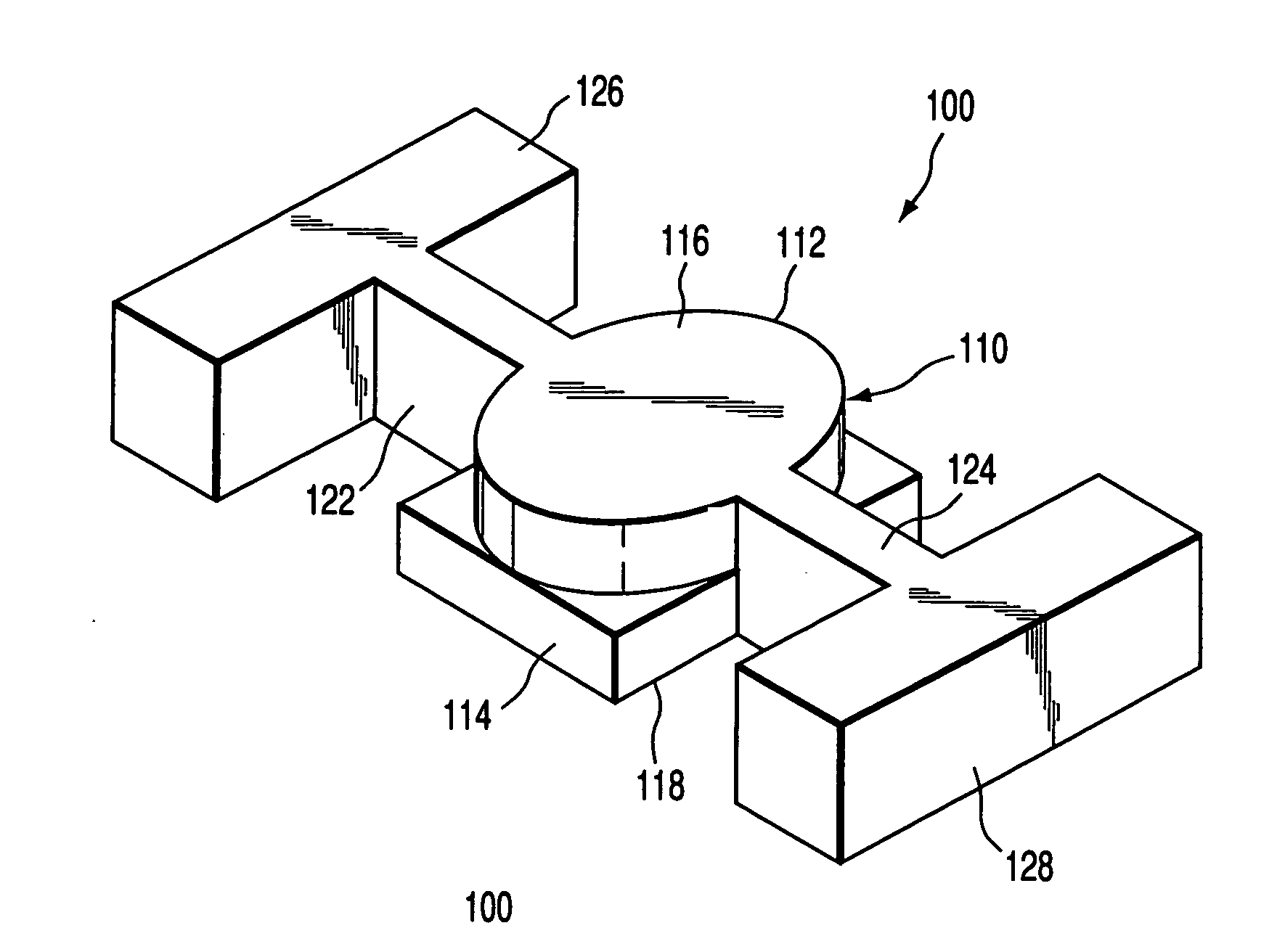
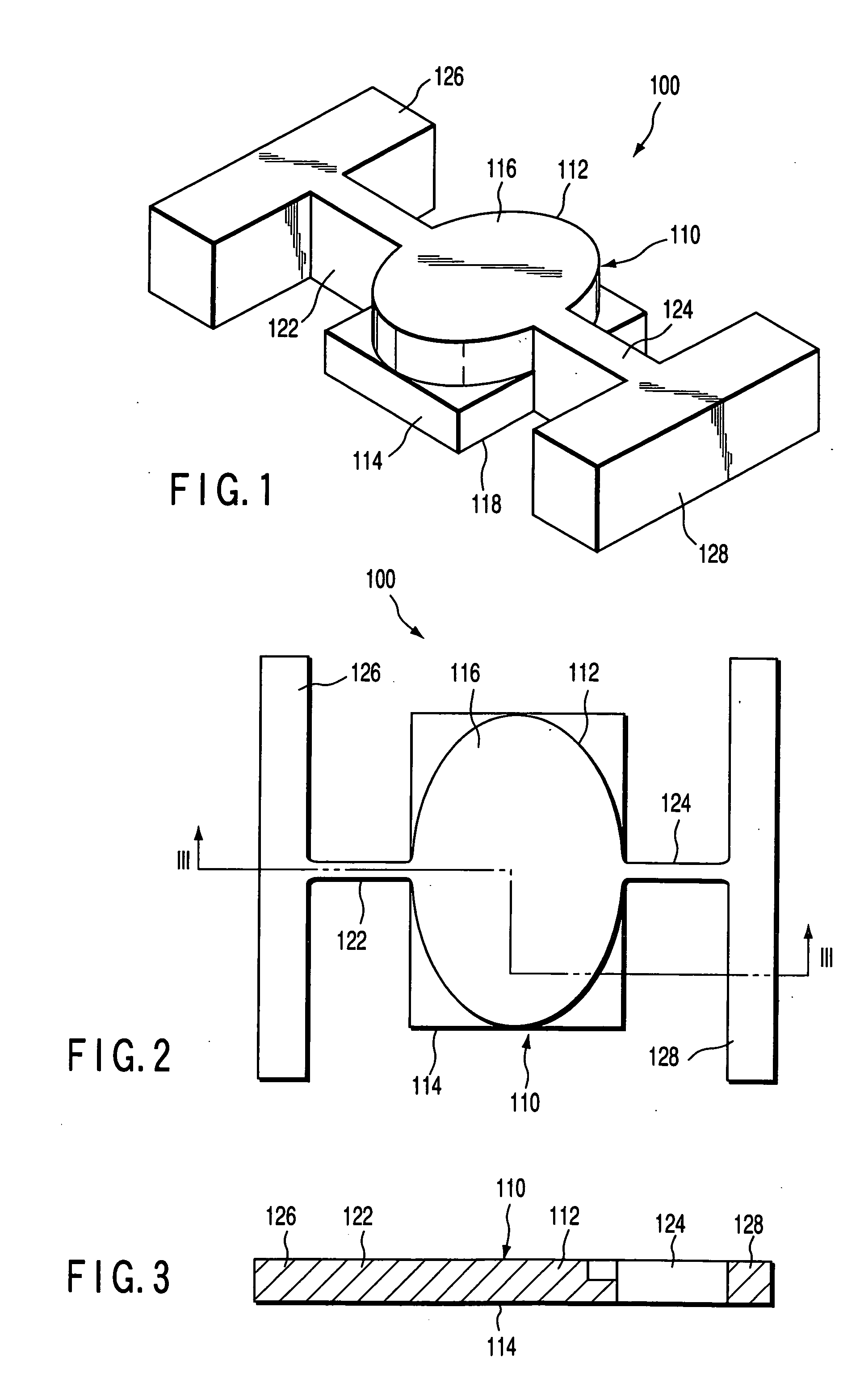
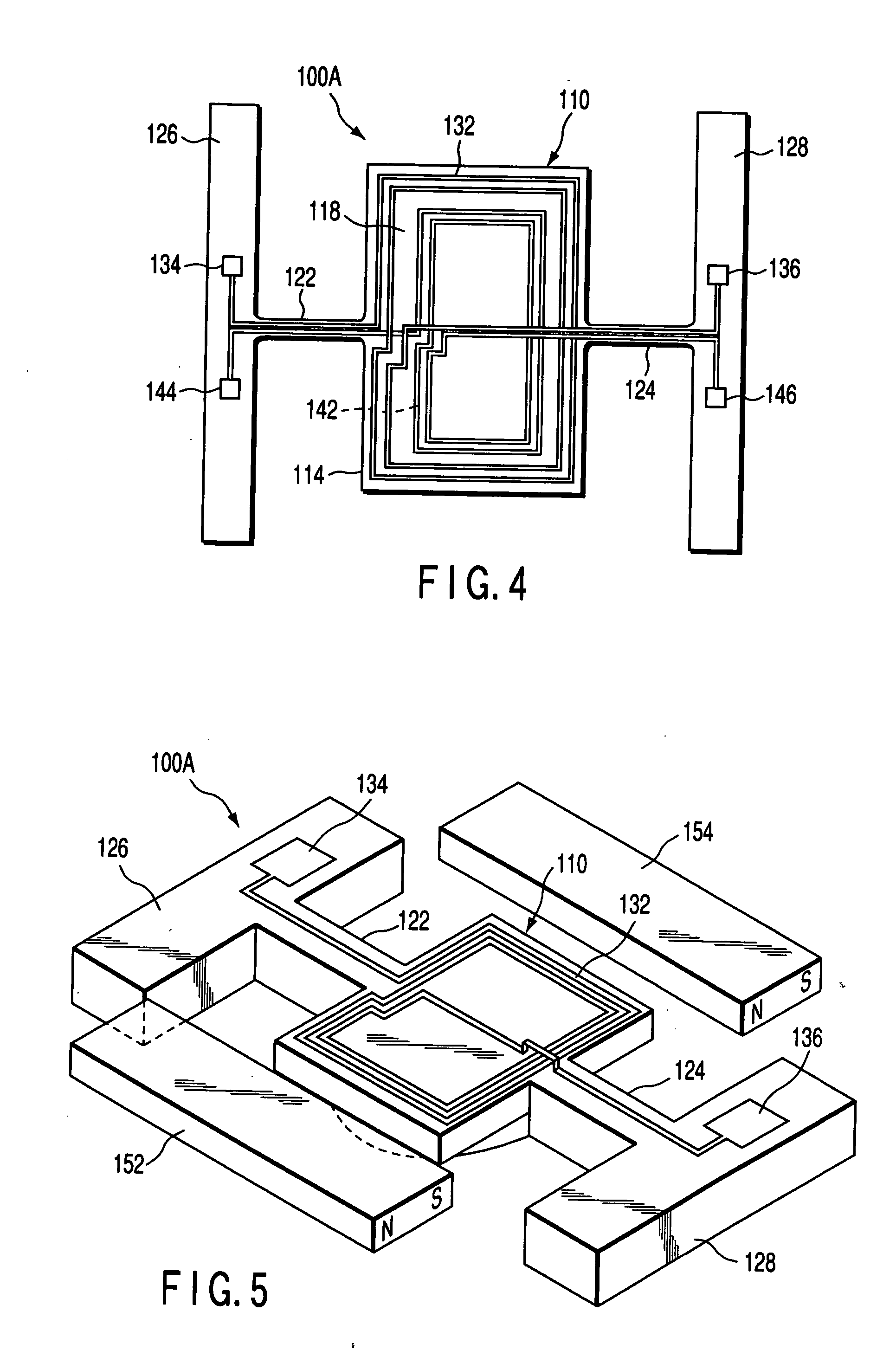
[0047] As shown in FIGS. 1 to 3, a mirror rocking member 100 comprises a movable plate 110 having a reflective surface, torsion bars 122, 124 as a pair of elastic members for rockably supporting the movable plate 110, and support members 126, 128 for supporting the torsion bars 122, 124. The torsion bars 122, 124 have rectangular sections, and symmetrically extend to opposite sides from the movable plate 110. Therefore, the movable plate 110 is rockably supported around a rocking axis passed through the torsion bars 122, 124 with respect to the support members 126, 128.
[0048] The movable plate 110 has a first portion 112 having the reflective surface, and a second portion 114 having an electric element, which constitutes a part of driving means for driving the mirror rocking member 100. The first portion 112 has a reflective-surface forming surface 116 with the reflective surface formed thereon, and s...
second embodiment
[0097] A second embodiment will next be described with reference to the drawings.
[0098] As shown in FIGS. 10 to 12, a mirror rocking member 200 comprises a movable plate 210 having the reflective surface, torsion bars 222, 224 as a pair of elastic members for rockably supporting the movable plate 210, and support members 226, 228 for supporting the torsion bars 222, 224. The torsion bars 222, 224 have rectangular sections, and symmetrically extend to opposite sides from the movable plate 210. Therefore, the movable plate 210 is rockably supported around the rocking axis passed through the torsion bars 222, 224 with respect to the support members 226, 228.
[0099] The movable plate 210 has a first portion 212 having the reflective surface, and a second portion 214 including an electric element constituting a part of the driving means for driving the mirror rocking member 200. As described in the first embodiment, the reflective surface may be a reflective-surface forming surface 216,...
third embodiment
[0117] A third embodiment will next be described with reference to the drawings.
[0118] As shown in FIGS. 16 and 17, a mirror rocking member 300 is a structure similar to the mirror rocking member 200 of the second embodiment, and comprises a movable plate 310 having the reflective surface, torsion bars 322, 324 as a pair of elastic members for rockably supporting the movable plate 310, and support members 326, 328 for supporting the torsion bars 322, 324. The torsion bars 322, 324 have rectangular sections, and symmetrically extend to opposite sides from the movable plate 310.
[0119] The movable plate 310 has a first portion 312 having the reflective surface, and a second portion 314 including an electric element constituting a part of the driving means for driving the mirror rocking member 300. The first portion 312 has a reflective-surface forming surface 316 with the reflective surface formed thereon, and side surfaces of the first portion 312 are inclined with respect to the re...
PUM
 Abstract
Description
Claims
Application Information
 - R&D
- Intellectual Property
- Life Sciences
- Materials
- Tech Scout
- Unparalleled Data Quality
- Higher Quality Content
- 60% Fewer Hallucinations
Browse by: Latest US Patents, China's latest patents, Technical Efficacy Thesaurus, Application Domain, Technology Topic, Popular Technical Reports.
© 2025 PatSnap. All rights reserved.Legal|Privacy policy|Modern Slavery Act Transparency Statement|Sitemap|About US| Contact US: help@patsnap.com


