
Retinal scanning display

a display and retina technology, applied in the field of retina scanning display, can solve the problem of difficult to eliminate such a pattern

Inactive Publication Date: 2011-01-20
BROTHER KOGYO KK
View PDF5 Cites 0 Cited by
  • Summary
  • Abstract
  • Description
  • Claims
  • Application Information

AI Technical Summary

Benefits of technology

[0008]It is an object of the present invention to provide a retinal scanning display which can prevent the periodic occurrence of a line-shaped pattern.

Problems solved by technology

However, the complete elimination of such a pattern is not easy.

Method used


Image

  • Retinal scanning display
  • Retinal scanning display
  • Retinal scanning display

Examples


Embodiment Construction

[0020]Hereinafter, preferred embodiments of the present invention are explained hereinafter in conjunction with drawings.

[Electrical Constitution of Image Display Device]

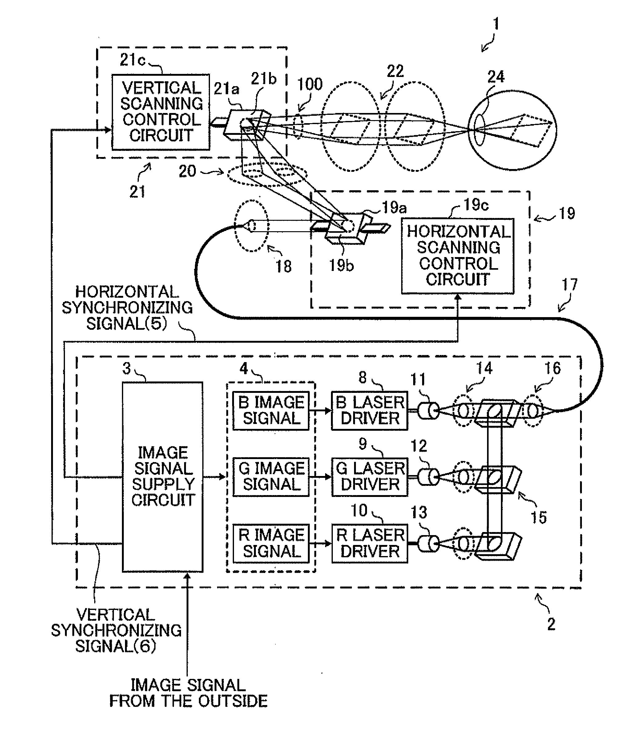
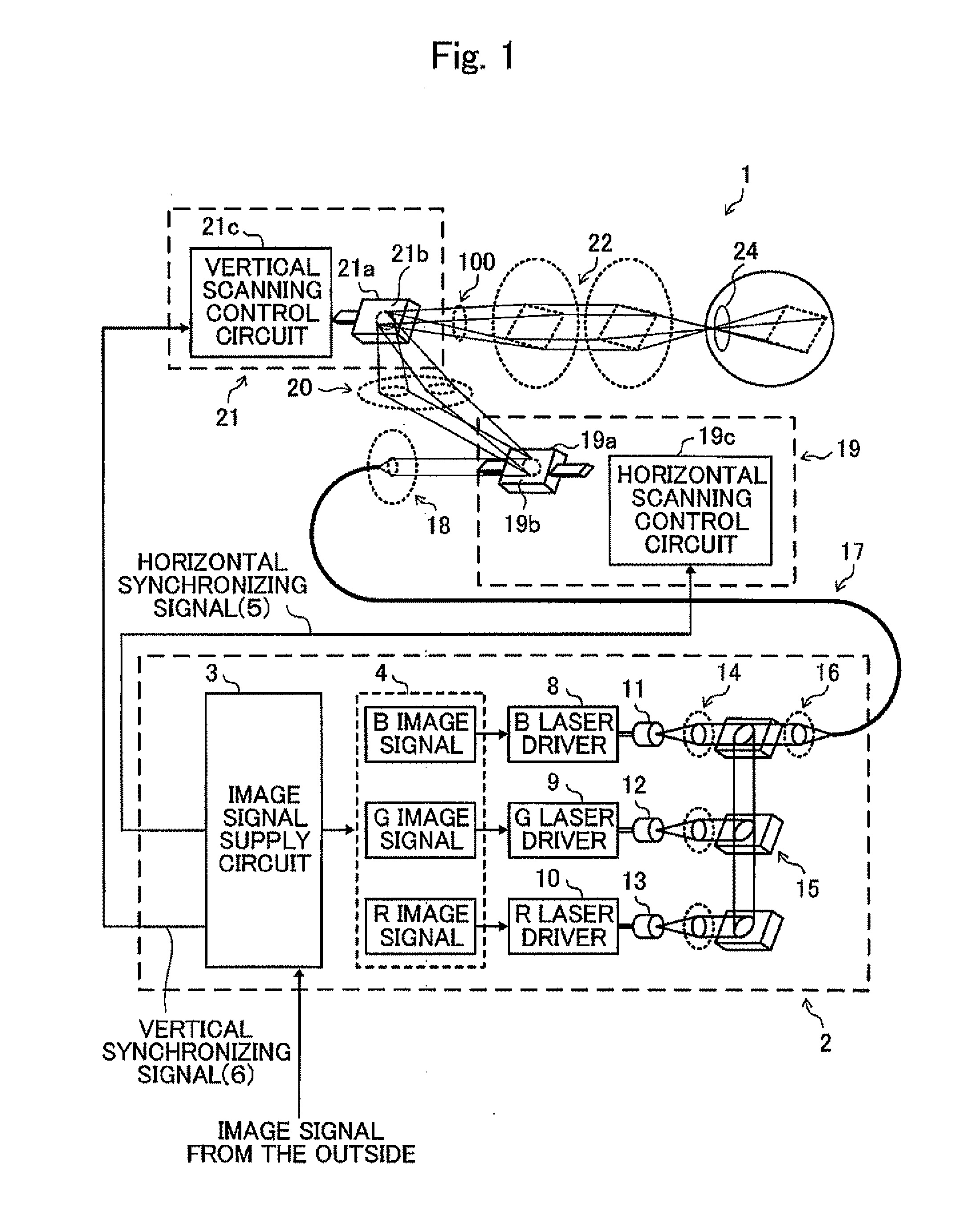
[0021]The electrical constitution of a retinal scanning display 1 of this embodiment or the like is explained in conjunction with FIG. 1.

[0022]As shown in FIG. 1, in the retinal scanning display 1, a light source unit part 2 is provided for processing image signals supplied from the outside. The light source unit part 2 includes an image signal supply circuit 3 to which the image signal is inputted from the outside. The image signal supply circuit 3 generates respective signals which become elements for synthesizing an image in response to the image signals. An image signal 4, a horizontal synchronizing signal 5 and a vertical synchronizing signal 6 are outputted from the image signal supply circuit 3. Further, the light source unit part 2 also includes an R laser driver 10, a G laser driver 9 and a B laser driver 8...


PUM


Abstract

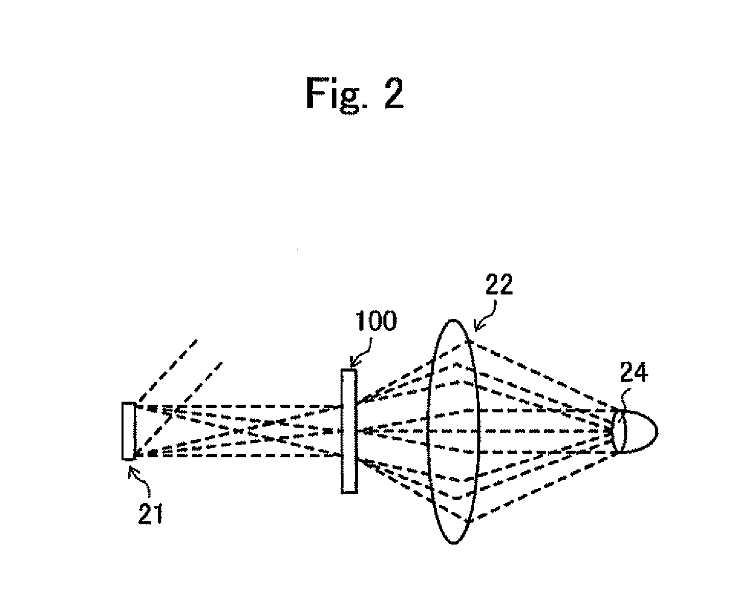
In a retinal scanning display, a light source part generates light modulated in response to an image signal relating to an image, and an image is displayed by scanning the light radiated from the light source part. The retinal scanning display includes a diffraction element which is arranged on an optical path of the light radiated from the light source part and diffracts light in a predetermined diffraction direction. The diffraction element is arranged such that the diffraction element is arranged such that a projection of a diffraction direction on the diffraction element with respect to a scanning direction of the scanning part becomes approximately 45 degrees.

Description

CROSS-REFERENCE TO RELATED APPLICATIONS[0001]The present application is a Continuation-in-Part of International Application PCT / JP2009 / 055084 filed on Mar. 16, 2009, which claims the benefits of Japanese Patent Application No. 2008-094163 filed Mar. 31, 2008.BACKGROUND[0002]1. Field[0003]The present invention relates to a retinal scanning display, and more particularly to a retinal scanning display which displays an image by scanning light modulated in response to an image signal relating to the image in the predetermined scanning directions.[0004]2. Description of the Related Art[0005]Conventionally, there has been known a device which displays an image in a visually recognizable manner by radiating light from a light source part modulated in response to an image signal to the outside as a radiation light. Further, there has been also known a retinal scanning display in which the light which is radiated to the outside in this manner is scanned in the predetermined scanning directio...

Claims


Application Information

Patent Timeline
IPC IPC(8): G02B26/10G02B27/44
CPCG02B7/003G02B26/101H04N9/3129G02B27/1086G02B27/145G02B27/104
Inventor TANAKA, MITSUGI
Owner BROTHER KOGYO KK
Learn More