Contact area measurement device and method for measuring contact area

a technology of contact area and measurement device, which is applied in the direction of phase-affecting property measurement, instruments, computing, etc., can solve the problems of poor accuracy in extracting a true contact area, inability to bring the contact area into focus very well, and limited material visualization

Active Publication Date: 2011-01-20
NSK WARNER +1
View PDF2 Cites 9 Cited by
  • Summary
  • Abstract
  • Description
  • Claims
  • Application Information

AI Technical Summary

Problems solved by technology

When a contrast method is used to visualize the real contact area, materials to be visualized are limited and the accuracy in extracting a true contact region is poor.
On the other hand, in the total reflection method, since a prism is used to observe a contact area obliquely, the aspect ratio of an image is not one and the contact area cannot be brought into focus very well.
In this case, the threshold setting and hence the extraction result differ person to person, and it takes a long time to carry out the whole procedure.
There is no obvious reason for directly applying the method to the problems described above, and the method is not applicable or accurate.
In a conventional method, since the region having intensity smaller than or equal to a threshold is extracted as a real contact area, it is difficult to rationally determine the threshold.
However, the above-described methods are problematic in that intensity values of the RGB three elements and the thresholds therefor, even though

Method used


Image

  • Contact area measurement device and method for measuring contact area
  • Contact area measurement device and method for measuring contact area
  • Contact area measurement device and method for measuring contact area

Examples


first embodiment

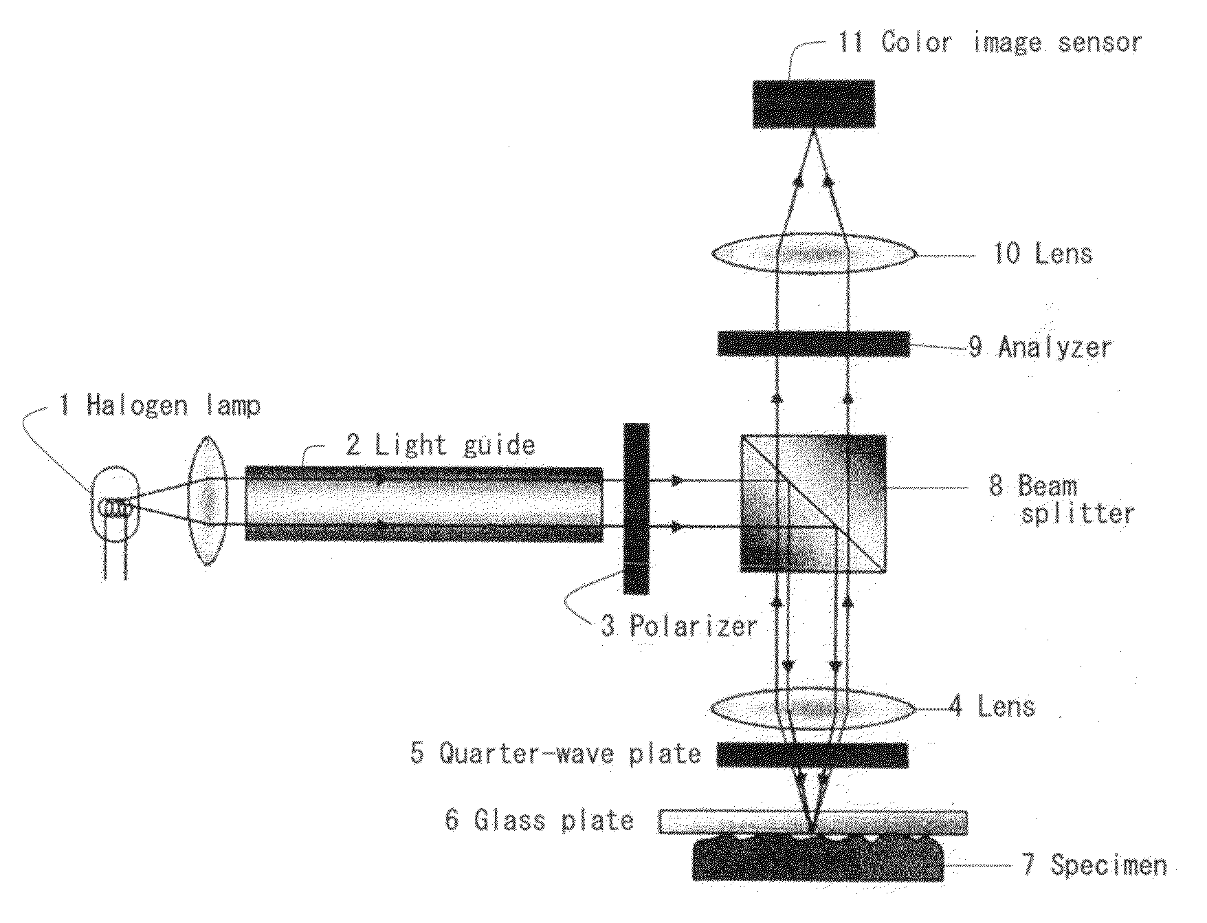
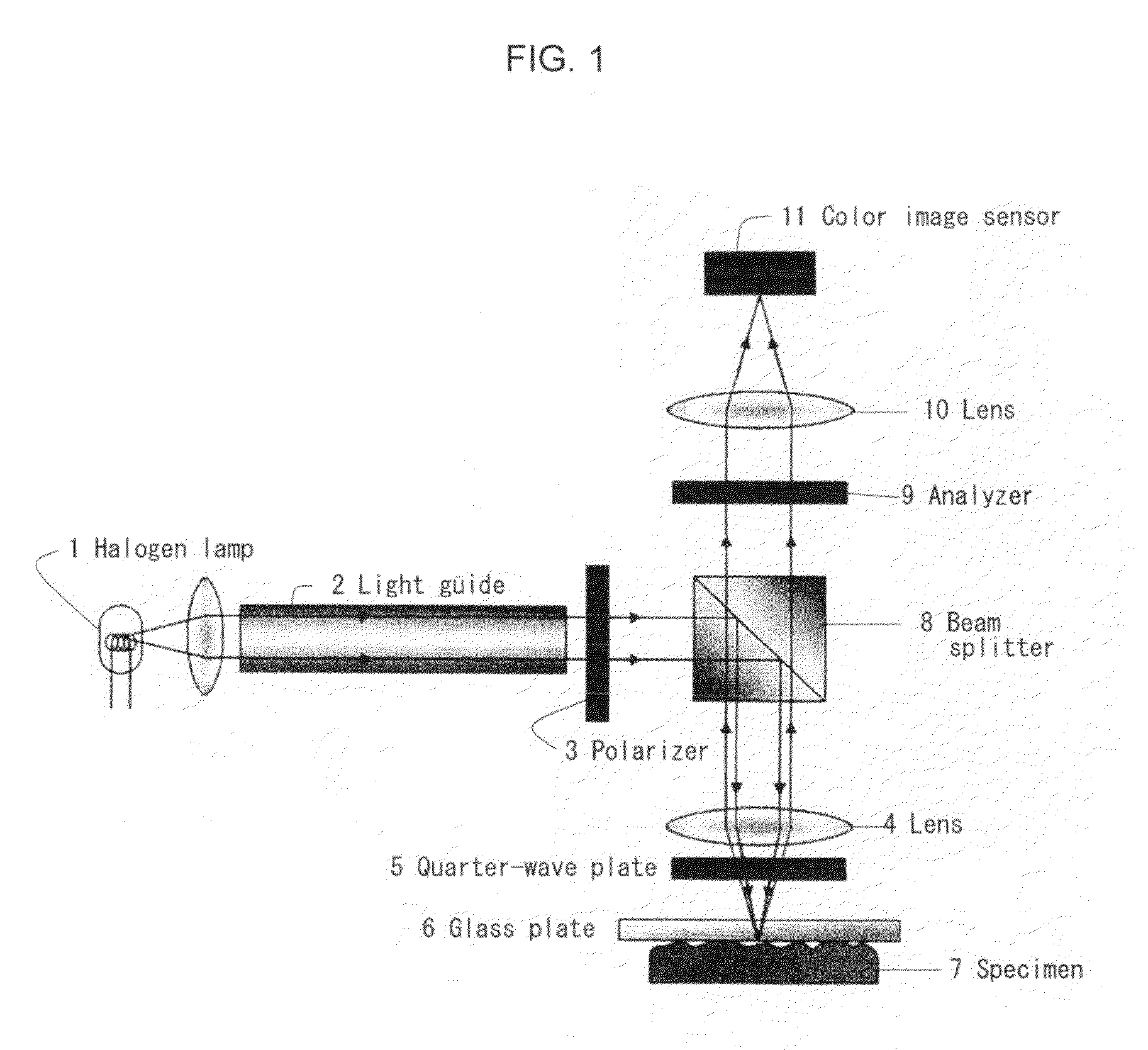
[0076]In the following, the description of a test piece according to the present invention is given. In the present example, a real contact area between two flat surfaces in contact with each other is approximated to point contact that occurs between a flat surface and a sphere. This approximation provides the following advantages: (1) a contact area can be clearly identified and visualized; (2) the physical properties and the shape of the test piece allow the Hertzian contact theory to be applied; and, (3) the reliability of the experimental apparatus used in a basic experiment can be evaluated.

[0077]Next, an upper test piece is described according to the first embodiment of the present invention. The upper test piece is formed of a glass plate because the upper test piece needed to be flat and transparent. In the preferred embodiment, the glass plate is made of fused quartz with 30 mm in outer diameter and 3.0 mm in thickness and had a surface roughness of 20 nm, Young's modulus o...

second embodiment

[0125]Next, a lower test piece is described according to the present invention. A thin rubber test piece is used as the lower test piece because it achieves a practical surface and practical friction conditions and in expectation that low modulus of elasticity of rubber may provide greater change in the behavior of the contact surface. The thin rubber test piece is obtained by stretching a natural rubber thin plate having a thickness of 0.5 mm and bonding it onto a steel hemisphere having a radius of 5 mm. It should be noted that the lower test piece is not limited to the thin rubber test piece as described above but can be a solid rubber test piece or a wet-paper-based frictional material.

[0126]The preprocessing performed on an acquired image will be described in detail in what follows. Information on the intensity of a captured image includes not only information on a contact surface and the vicinity thereof obtained by using optical interferometry, but also may include informatio...


PUM


Abstract

A novel contact area measuring apparatus is provided. The contact area measuring apparatus includes a light transmissive substrate 6 in contact with a specimen 7, illumination means for illuminating the light transmissive substrate 6 with white light from the opposite side of the light transmissive substrate 6 to the specimen 7, interference image acquisition means 11 for acquiring an interference image produced by the light reflected off the specimen 7 and the light reflected off the light transmissive substrate 6, intensity histogram creation means for creating an intensity histogram from information on the intensity of the interference image, and contact area computation means for calculating a contact area from the intensity histogram. The interference image acquisition means 11 acquires an interference image and information on the intensity of the interference image. The intensity histogram creation means forms separate RGB intensity information from the information on the intensity of the interference image and creates a G-intensity histogram. The contact area computation means separates the intensity histogram into a plurality of normal distributions by using optimized approximation of complex normal distribution and calculates the contact area from the lowest-intensity normal distribution.

Description

[0001]This application is a National Stage application under 35 U.S.C. §371 of International Application Serial No. PCT / JP2009 / 053222, filed on Feb. 23, 2009, and claims the priority benefit under 35 U.S.C. §119 of Japanese Patent Application No. 2008-067584, filed Mar. 17, 2008, and Japanese Patent application Serial No. 2008-199469, filed Aug. 1, 2008, which are hereby expressly incorporated by reference in their entirety for all purposes.TECHNICAL FIELD[0002]The present invention relates to a novel contact area measuring apparatus and method. More specifically, it relates to a novel apparatus and method for visualizing a contact area between two surfaces in contact with each other and statistically extracting a real contact area from the visualized image based only on an intensity histogram of the image without requiring a threshold for binarization. The invention also relates to a novel apparatus and method for measuring and visualizing the distribution of a stick region and a s...

Claims


Application Information

Patent Timeline
IPC IPC(8): G06K9/00
CPCG01B11/28G01N2015/1075G01N21/45G01B11/285
Inventor EGUCHI, MASAOSHIBAMIYA, TAKASHISAWAYANAGI, MANABUMIYAZAKI, TOMOYUKI
Owner NSK WARNER
Why Eureka
Try Eureka