Fan array control system

Active Publication Date: 2011-01-20
NORTEK AIR SOLUTIONS
View PDF3 Cites 40 Cited by
  • Summary
  • Abstract
  • Description
  • Claims
  • Application Information

AI Technical Summary

Problems solved by technology

These prior art air-handling systems have many problems including the following exemplary problems:
Because real estate (e.g. structure space) is extremely expensive, the larger size of the air-handling compartment 102 is extremely undesirable.
The single fan units 100 are expensive to produce and are generally custom produced for each job.
Single fan units 100 are expensive to operate.
Single fan units 100 are inefficient in that they only have optimal or peak efficiency over a small portion of their operating range.
The high m

Method used


Image

  • Fan array control system
  • Fan array control system
  • Fan array control system

Examples


first embodiment

[0088]Turning first to the first embodiment shown in FIGS. 17-19, this layered embodiment includes a fiberglass core 22 (or other type of insulation) that has an open cell foam 24 layered with at least one side of the fiberglass core 22. One advantage to using both the fiberglass material and the open cell foam material is that it is less expensive than using open cell foam material alone because open cell foam more expensive than fiberglass. Another advantage to using both the fiberglass material and the open cell foam material is that it weighs less than using fiberglass material alone because fiberglass weighs more than open cell foam. Another advantage to using both the fiberglass material and the open cell foam material is that is that the two materials provide different types of acoustic insulation over a different range of frequencies. Together, the two materials provide sound absorption over greater range of frequencies. The graph below (shown with a vertical axis as the abs...

second embodiment

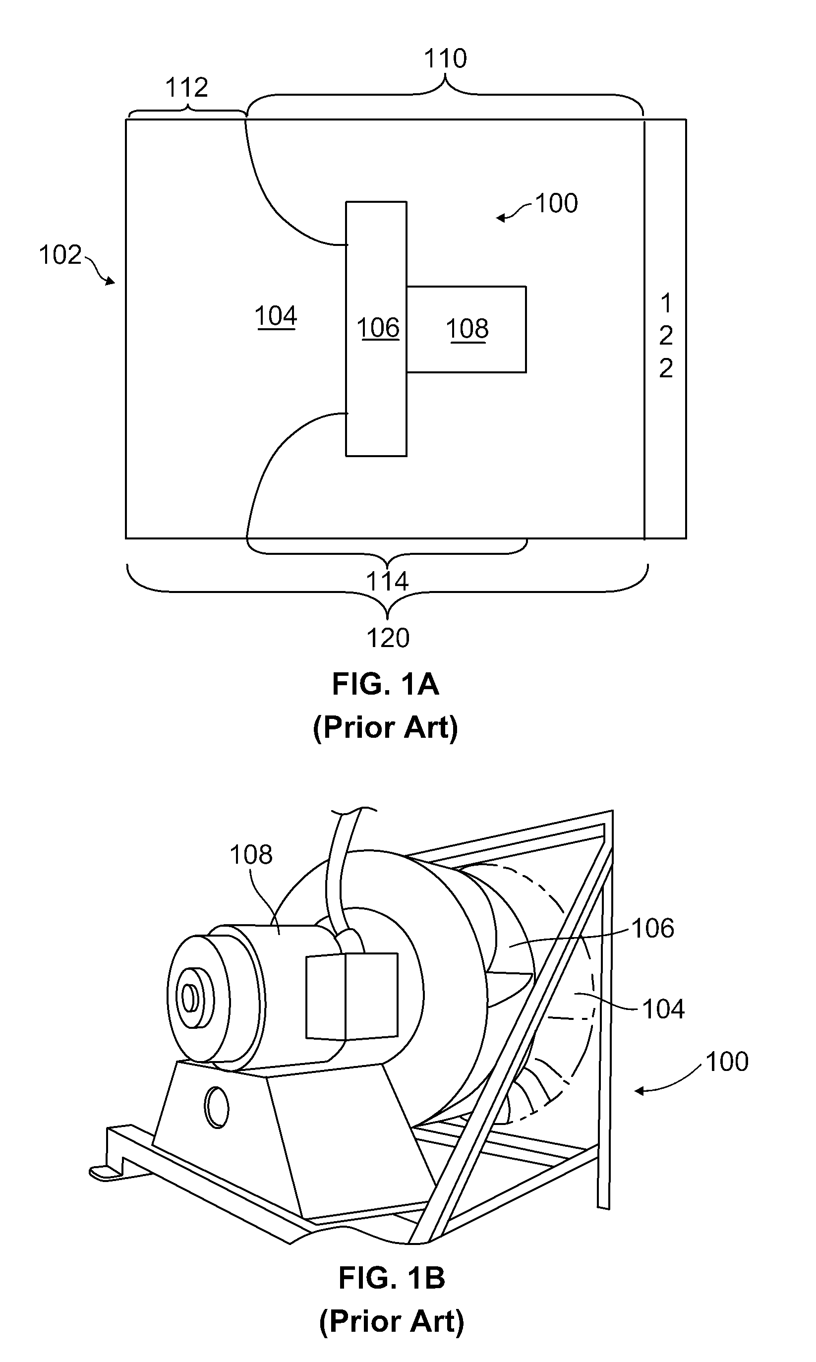
[0091]Turning next to the second embodiment shown in FIGS. 17 and 19-22, this perf-secured embodiment combines the use of open cell fawn 24 with for use of perforated rigid facing 26. Combining the use of open cell foam and perforated rigid facing 16 provides significant advantages for use in air handlers. For example, the use of thee perforated rigid facing 26 to secure the open cell foam 24 does not significantly reduce the sound, absorption qualities of the open cell foam 24. As shown in FIG. 20, the open cell structure of the open cell foam 24 allows portions of the open cell foam 24 to protrude from openings defined in the perforated rigid facing 26 (shown in front view in FIG. 21). The exposed open cell foam 24 is able to absorb sound waves. In one embodiment, protruding open cell foam 24 formed between the openings in the perforated rigid facing 26 absorbs sound waves. This can be compared to prior art embodiments in which sound waves are reflected by the substantially rigid ...

third embodiment

[0095]The present invention also includes a method for making an air handler using the uncoated The method includes the steps of providing an air handler system with at least one air handler surface and open cell foam. The method also includes the step of covering at least partially the at least one air handler surface with the open cell foam.

[0096]The present invention is directed to the use of open cell foam in air handlers that has the necessary durability, safety, and cleanliness properties for the particular use. One exemplary open cell foam, melamine foam (Melamine-Formaldehyde-Polycondensate), has been shown to be quite suitable for this purpose. Melamine is a lightweight, high temperature resistant, open cell foam that has excellent thermal properties with superior sound absorption capabilities. Melamine is cleanable in that it is relatively impervious to chemicals (e.g. it is able to withstand relatively caustic cleaning agents such as SPOR-KLENZ® without breaking down). M...


PUM


Abstract

A fan array fan section in an air-handling system includes a plurality of fan units arranged in a fan array and positioned within an air-handling compartment One preferred embodiment may include an array controller programmed to operate the plurality of fan units at peak efficiency by computing the power consumed in various configurations and selecting the configuration requiring minimum power to operate.

Description

CROSS-REFERENCE TO RELATED APPLICATIONS[0001]This application claims priority to U.S. Provisional Patent Application 61 / 255,364 filed Oct. 27, 2009, which is a Continuation-In-Part of U.S. patent application Ser. No 12 / 079,177, filed Mar. 24, 2008, which is a continuation of U.S. patent application Ser. No 11 / 595,212, filed Nov. 9, 2006, now U.S. Pat. No. 7,527,468, which is a Continuation of U.S. patent application Ser. No. 10 / 806,775, filed Mar. 22, 2004, now U.S. Pat. No. 7,137,775, which is a Continuation-In-Part of PCT Patent Application Ser. No. PCT / US2004 / 08578, filed Mar. 19, 2004, and claims the benefit of U.S. Provisional Patent Application Ser. No 60 / 456,413, filed Mar. 20, 2003, and U.S. Provisional Patent Application Ser. No. 60 / 554,702, filed Mar. 20, 2004. All of the above-referenced applications are hereby incorporated by reference in their entirety.BACKGROUND OF THE INVENTION[0002]The present invention is directed to a fan array fan section utilized in an air-handli...

Claims


Application Information

Patent Timeline
IPC IPC(8): F04D15/02
CPCF04D25/166F24F2011/0075F04D27/0207F24F3/0442F24F7/06F24F11/0079F24F2011/0038F24F2011/0041H01M2/0277H01M2/08H01M2/1094H04W28/04H04W88/02Y02B30/746H04W52/0219H04W52/0258Y02B30/767F04D27/004F04D15/0066F04D15/0281F24F11/001F24F11/006F24F2011/0047F04D27/02F04D29/663F24F11/30F24F2110/40F24F2110/30F24F11/77F24F11/62F24F11/46F24F2110/00F24F2140/60F24F11/72Y02B30/70Y02D30/70Y02E60/10H01M50/24F24F11/65F04D27/00F04D25/16H05K7/20F04D15/00F04D29/14F04D29/601G05B2219/2614
Inventor HOPKINS, LAWRENCE G.MOTLAND, BRIAN JAMESGASSAWAY, MATTHEW ALAN
Owner NORTEK AIR SOLUTIONS
Why Eureka
Try Eureka