Method for protecting a substrate from lightning strikes

a technology of electrical conductivity and substrate, applied in shielding materials, electrically conductive paints, instruments, etc., can solve the problems of increasing vulnerability, affecting avionics, and affecting the electrical conductivity of composite materials, so as to improve thermal and electrical conductivity, reduce filler loading, and eliminate contact resistance

Inactive Publication Date: 2011-01-20
LORD CORP
View PDF76 Cites 52 Cited by
  • Summary
  • Abstract
  • Description
  • Claims
  • Application Information

AI Technical Summary

Benefits of technology

[0017]In an additional embodiment of the present invention, the lightning strike protectant composition further provides shielding of electromagnetic radiation having a frequency of between 1 MHz and 20 GHz, wherein said shielding reduces the electromagnetic radiation by at least 20 decibels.
[0028]In a further embodiment of the present invention, the self-assembled composition further provides secondary protection to a substrate. For example, though an initial lightning strike may create physical damage in the immediate area of the strike, electrical current may surge throughout the substrate / structure and damage distant electrical components or surfaces. The self-assembled conductive material of the present invention provides a means for dissipating and controlling this electrical surge in addition to providing primary protection to the immediate area of the strike.

Problems solved by technology

Although this affords significantly increased fuel efficiency and / or greater payload capacity, aircraft structures unfortunately become more vulnerable to lightning damage.
This increased vulnerability is rooted in the inferior electrical conductivity of composites, such as those based on carbon fiber reinforced materials, relative to that of aluminum metal.
Direct effects are associated with physical or “direct” damage to load bearing structures, with the worst types of damage being severe punctures through composites laminates.
These surges can disrupt avionics and in turn compromise the pilot's ability to control the aircraft.
These approaches, although much more efficient at increasing conductivity relative to heavily filled resins, they still lack the ultimate conductivity and current carrying capacity needed in LSP applications.
Unfortunately, these and the above-mentioned materials still suffer from limited strike protection, substantial weight gain, manufacturing challenges, and / or limitations in basic properties such as thermal and electrical conductivity, current carrying capacity, viscosity (or handling), and / or mechanical properties.
Despite their presence in a majority of fixed and rotary wing aircraft, EMFs possess a number of undesirable features.
For example, EMF systems exhibit limited “indirect protection” by providing shielding over a limited range of frequencies.
Because of this, aircraft designers often add extra or more robust shielding materials to the aircraft to safeguard against disruptions in electrical communications which in turn adds considerable weight.
EMF systems also suffer from handling issues during manufacturing and repairs.
Specifically, EMFs must be integrated with adhesives films at the supplier or the original equipment manufacturer (OEM) which can be challenging and costly.
Furthermore, EMFs are difficult to conform to contoured tooling, suffer tack issues, and are easily wrinkled and damaged during normal handling and cutting operations.
There are also issues in maintaining electrically integrity between panels during joining, splicing, and grounding operations.
It for such reasons, OEMs are forced to lay up these materials by hand, thereby leading to consider labor time and cost.
Numerous attempts have been made to automate layup of EMF with little success owing to these same issue in addition weight penalties due the overlapping EMF at many splices.
In addition to handling, metal meshes based on aluminum and copper are prone to corrosion owing to differences in galvanic potentials between the metal and the underlying carbon.
Unfortunately, adding plies adds extra steps, increases labor, costs, and adds more weight to the aircraft.
Repair is also an issue with EMF systems.
Splicing of the new foil to the existing foil such that the conductive pathways align is again a challenge as well as dealing with porosity effects arising from air entrapment.

Method used


Image

  • Method for protecting a substrate from lightning strikes
  • Method for protecting a substrate from lightning strikes
  • Method for protecting a substrate from lightning strikes

Examples


example 1

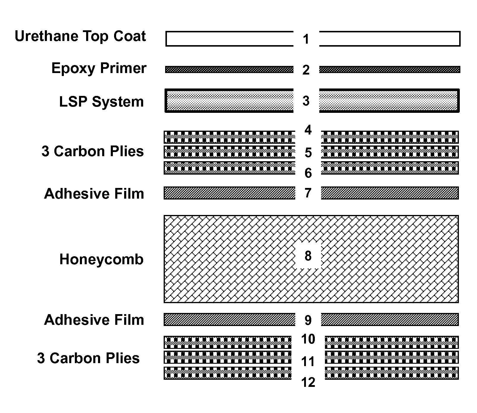
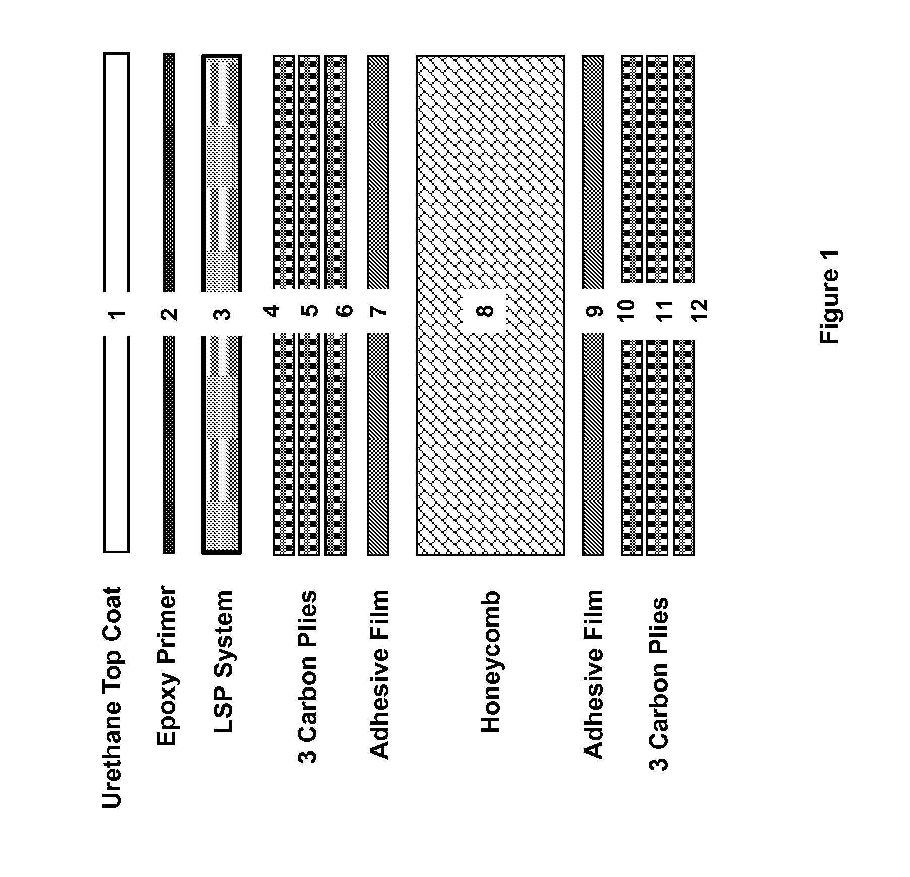
[0086]Table 2 compares the Zone 1A strike results for various LSP systems (represented pictorially by Layer 3 in FIG. 1). Specific details of the various panels and corresponding LSP systems are as follows: Panel A contained no lightning strike protection system, i.e. Layer 3 (see FIG. 1) was absent during panel construction. Panels B and C (State of Art) were compromised of aluminum and copper Expanded Metal Foils (EMF) that were supplied pre-embedded in a surfacing adhesive film (SG4528-016AL-104V and SG4528-04CU-103V, respectively, from APCM-AME, Plainfield, Conn.) which was further combined with a glass-fiber isolation ply (FGF108-29M-990, Toray Composites America, Inc). The isolation ply was situated between the EMF-adhesive film and topmost carbon fiber layer (Layer 4 in FIG. 1). Ref1 and Ref2 provide additional EMF data previously reported by Welch et al of Spirit AeroSystems (SAMPE Journal, Vol. 44, No. 4, July / August 2008, pp. 6-17). The panels described in this report are ...

example 2

[0098]Table 3 compares the Zone 2A strike results for various LSP systems (represented pictorially by Layer 3 in FIG. 1). Panel G (State of Art) was compromised of aluminum EMF (Grade 016, Pacific Coast Composites) that was combined with a film adhesive (HCS2404-050, 242 g / m2, Heatcon® Composites) which was further combined with a glass-fiber isolation ply (FGF108-29M-990, Toray Composites America, Inc). The isolation ply was situated between the EMF-adhesive film and topmost carbon fiber layer. Panel H was prepared in the same manner as Panel F except using the following ingredients for conductive paste and solvent blend. Conductive paste: 25.1 wt % diglycidyl ether of bisphenol F, 9.6 wt % amine adduct curative, and 65.3 wt % silver flake (17% by volume). Solvent blend: 50% acetone, 18% toluene, 16% methyl ethyl ketone, 11% ethyl acetate, and 5% ligroine, by weight.

[0099]Although both panels in Table 3 prevent catastrophic failure and demonstrate acceptable Action Integrals (i.e.,...

example 3

[0100]As previously mentioned, the self-assembling nature of the materials of the present invention have the ability to form continuous, conductive pathways during the curing of material. This feature is especially unique as it enables one to electrically bridge interfaces (e.g. a splice between two adjacent sections) that are commonly encountered in the original construction of structures and during the repair of existing ones. Furthermore, this method enables one to automate the LSP manufacturing process. State of art materials based on metal foils lack the ability to form continuous interfaces at splice, which often leads to very large electrical resistances across interfaces between separate LSP EMFs. Moreover, automated of these LSP is prohibited owing to splice issues, fragility, and weight issues.

[0101]To illustrate the ability of the present invention to electrically bridge interfaces, the same self-assembling LSP material for Panel H was spray coated onto two different 10 c...


PUM

PropertyMeasurementUnit
frequencyaaaaaaaaaa
frequencyaaaaaaaaaa
frequenciesaaaaaaaaaa

Abstract

A method for protecting a substrate from lightning strikes is provided including providing a lightning strike protectant composition to the substrate. The lightning strike protectant composition comprises a reactive organic compound and a conductive filler that, during the cure of the organic compound, is capable of self-assembling into a heterogeneous structure comprised of a continuous, three-dimensional network of metal situated among (continuous or semi-continuous) polymer rich domains. The resulting composition has exceptionally high thermal and electrical conductivity.

Description

CROSS-REFERENCE TO RELATED APPLICATIONS[0001]The present application claims priority under 35 U.S.C. §119(e) from U.S. Provisional Patent Application Ser. No. 61 / 186,415 filed Jun. 12, 2009, entitled “CURABLE CONDUCTIVE MATERIAL FOR LIGHTNING STRIKE PROTECTION”, and U.S. Provisional Patent Application Ser. No. 61 / 186,492 filed Jun. 12, 2009, entitled “ELECTROMAGNETIC SHIELDING MATERIALS”, the disclosures of which are incorporated herein by reference.FIELD OF THE INVENTION[0002]The present invention relates to electrically conductive polymeric materials.[0003]More particularly, the present invention relates to electrically conductive compositions used for lightning strike protection (LSP).BACKGROUND OF THE INVENTION[0004]Owing to excellent combinations of strength and weight, composite materials are being increasing used to replace aluminum in aircraft structures. Although this affords significantly increased fuel efficiency and / or greater payload capacity, aircraft structures unfort...

Claims


Application Information

Patent Timeline
Patent Type & Authority Applications(United States)
IPC IPC(8): B05D5/12G01R31/02C09D7/62
CPCH05K9/0083C09D5/24C09D7/62C09D7/70B05D1/02C08L63/00C09D163/00C09D7/40H01B1/22C08G59/245C08G59/58C08K9/04H05K9/0079
Inventor FORNES, TIMOTHY D.CARRUTHERS, SETH B.HUFFMAN, NICOLAS D.
Owner LORD CORP
Why Eureka
Try Eureka