Multiband wireless terminal antenna

A wireless terminal, multi-band technology, used in antennas, antenna grounding devices, devices that make antennas work in different bands at the same time, etc. Broadband performance, the effect of reducing the footprint

Inactive Publication Date: 2013-01-02
UNIV OF ELECTRONICS SCI & TECH OF CHINA
View PDF3 Cites 23 Cited by
  • Summary
  • Abstract
  • Description
  • Claims
  • Application Information

AI Technical Summary

Problems solved by technology

[0004] The purpose of the present invention is to provide a multi-band wireless terminal antenna with small volume, high precision and convenient use, which mainly solves the problem that the antennas in the prior art cannot meet people's requirements for miniaturization, high precision and ease of use

Method used


Image

  • Multiband wireless terminal antenna
  • Multiband wireless terminal antenna

Examples


Embodiment

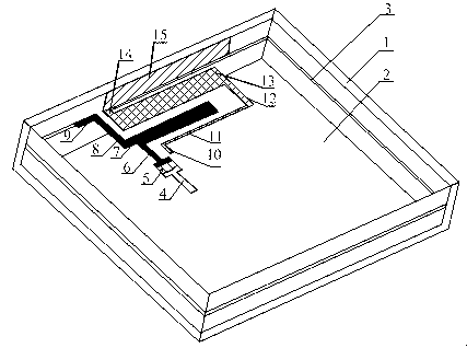
[0026] Such as figure 1 As shown, the multi-band wireless terminal antenna includes a housing 1, a printed board 2, a printed board metal ground 3, a microstrip feeder 4, a stop band 5, a high-frequency resonant metal strip group, and a low-frequency resonant metal strip group. Wherein, the printed board 2 is arranged in the casing 1, the printed board metal ground 3 is arranged on one surface of the printed board 2, the high-frequency resonant metal bar group and the low-frequency resonant metal bar group corresponding to the high-frequency resonant metal bar group Both are arranged on the other surface of the printed board 2 , the microstrip feeder 4 is connected to the end of the high-frequency resonant metal strip group, and the stop band 5 is connected between the high-frequency resonant metal strip group and the microstrip feeder 4 .

[0027] In the present invention, the high-frequency resonant metal strip group and the low-frequency resonant metal strip group are not ...


PUM


Abstract

The invention discloses a multiband wireless terminal antenna, mainly solving the problems that the antenna in the prior art can not meet the requirements of people for miniaturization, high accuracy and convenience in use. The multiband wireless terminal antenna comprises a shell, a printed board and a printed board metal floor and also comprises a high-frequency resonance metal strip group, a low-frequency resonance metal strip group, a microstrip feeder and a stop band, wherein the printed board is arranged in the shell; the printed board metal floor is arranged on one surface of the printed board; the high-frequency resonance metal strip group is arranged on the other surface of the printed board; the low-frequency resonance metal strip group corresponds to the high-frequency resonance metal strip group; the microstrip feeder is connected with the end part of the high-frequency resonance metal strip group; the stop band is connected between the high-frequency resonance metal strip group and the microstrip feeder; and a coupling gap is arranged between the high-frequency resonance metal strip group and the low-frequency resonance metal strip group. By the scheme, the multiband wireless terminal antenna has the advantages that the purposes of small volume, high accuracy and convenience in use are achieved and the practical and promotional values are high.

Description

technical field [0001] The invention relates to a terminal antenna, in particular to a multi-band wireless terminal antenna. Background technique [0002] With the rapid development of the economy and the continuous updating of technology, the application of various wireless terminal equipment has become increasingly popular in people's life, entertainment, and office. Among them, the antenna for receiving radio is an indispensable less part. [0003] At present, people mainly use external antennas or patch antennas for signal reception. However, such antennas are large in size, poor in strength, and not beautiful enough to meet people's requirements for miniaturization of wireless terminal antennas and multi-band work. Although the existing printed board antenna has the advantages of small size, light weight and high strength, this kind of antenna still occupies a large area in actual use, and the design that occupies the edge of the circuit board is more, which is not con...

Claims


Application Information

Patent Timeline
Patent Type & Authority Applications(China)
IPC IPC(8): H01Q1/38H01Q1/48H01Q5/01H01Q5/10
Inventor 杨顺王朗李乐伟刘佳奇班永灵
Owner UNIV OF ELECTRONICS SCI & TECH OF CHINA
Why Eureka
Try Eureka