High performance gas turbine inlet filter (HEPA) using membrane media

Active Publication Date: 2011-01-27
PARKER INTANGIBLES LLC
View PDF13 Cites 26 Cited by
  • Summary
  • Abstract
  • Description
  • Claims
  • Application Information

AI Technical Summary

Benefits of technology

[0011]In accordance with one aspect, the present invention provides a composite filter media structure that includes a base substrate. The base substrate includes a nonwoven fabric substrate formed from a plurality of bicomponent synthetic fibers using a spunbond process. The composite filter media structure includes a surface layer deposited on one side of the base where the surface layer is formed from a microporous expanded polytetrafluoroethylene membrane. The base substrate and the surface layer are configured to provide greater than 95% and equal to or less than 99.5% filtration efficiency measured in accordance with an EN 1822 test method.
[0012]In accordance with another aspect, the present invention provides a composite filter media structure that includes a gas turbine air inlet filter element. The gas turbine air inlet filter element includes a first end cap, a second end cap, and a filter media. The filter media includes a nonwoven fabric formed from a plurality of bicomponent synthetic fibers with a spunbond process and a surface laye

Problems solved by technology

However, the electrically charged nonwoven meltblown layer is known to reduce in performance significantly when exposed to moist environments and the electro-static charge diminishes quickly.
This known media has not been approved to meet the strict industry test protocols needed for pulsed Gas Turbine Inlet Filtration.
The wet laid glass based media may be unsuitable for use in pulsed filtration due to its inherent weak strength properties that cannot withs

Method used


Image

  • High performance gas turbine inlet filter (HEPA) using membrane media
  • High performance gas turbine inlet filter (HEPA) using membrane media
  • High performance gas turbine inlet filter (HEPA) using membrane media

Examples


Embodiment Construction

[0026]Example embodiments that incorporate one or more aspects of the present invention are described and illustrated in the drawings. These illustrated examples are not intended to be a limitation on the present invention. For example, one or more aspects of the present invention can be utilized in other embodiments and even other types of devices. Moreover, certain terminology is used herein for convenience only and is not to be taken as a limitation on the present invention. Still further, in the drawings, the same reference numerals are employed for designating the same elements.

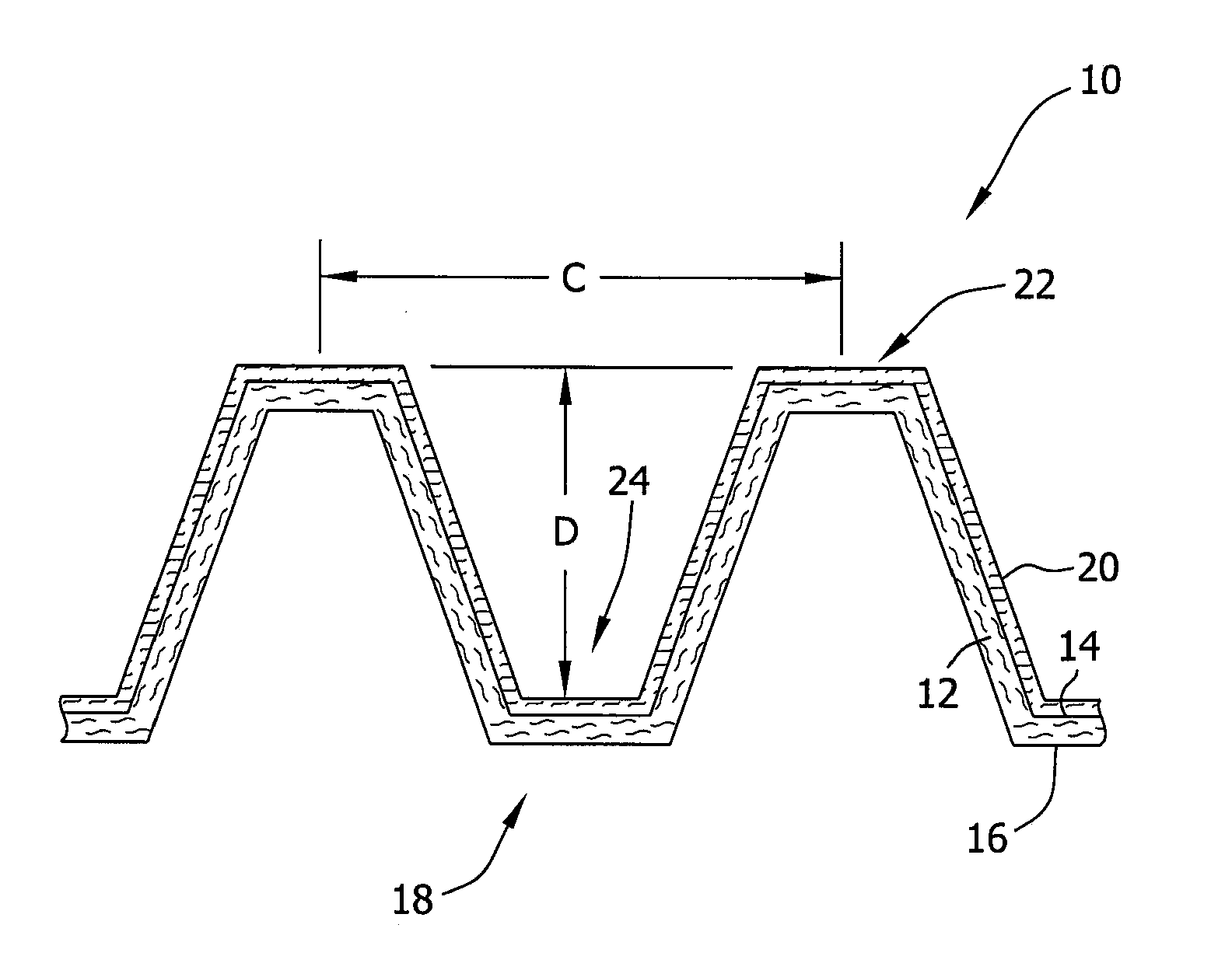
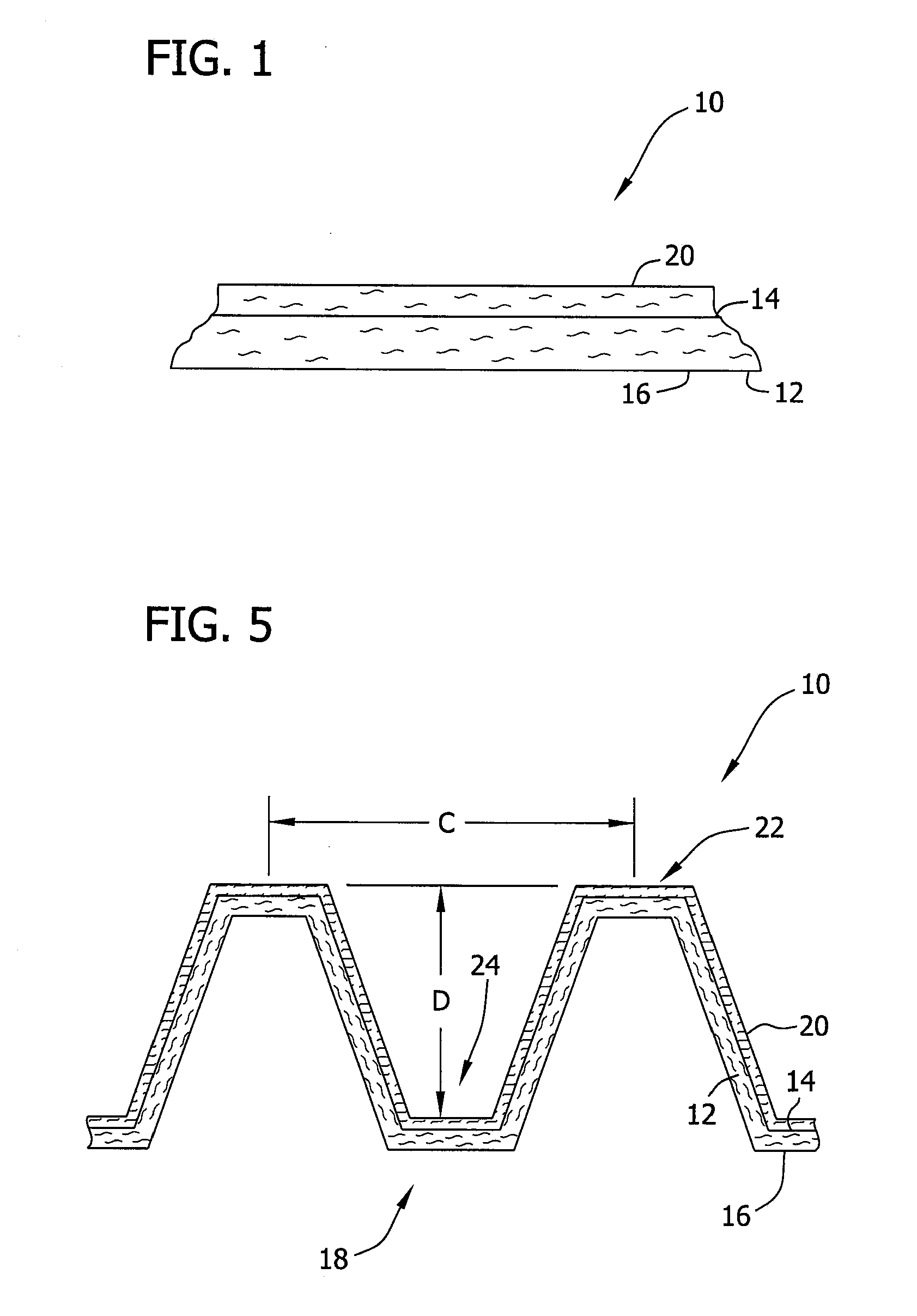
[0027]Examples of a high performance composite filter media and a method of making the composite filter media in accordance with one or more aspects of the present invention are described in detail below. In general, the composite filter media includes a bicomponent synthetic nonwoven base substrate and at least one surface layer. In one specific example, such composite filter media provides enhanced fil...


PUM

PropertyMeasurementUnit
Temperatureaaaaaaaaaa
Lengthaaaaaaaaaa

Abstract

A composite filter media structure and an associated method of making are provided. The structure includes a base substrate that includes a nonwoven fabric substrate formed from a plurality of bicomponent synthetic fibers using a spunbond process. The composite filter media structure includes a surface layer deposited on one side of the base substrate where a thermal lamination process can be used to combine the base substrate and the surface layer. The surface layer is formed from a microporous expanded polytetrafluoroethylene membrane. In one aspect, the base substrate and the surface layer are configured to provide greater than 95% and equal to or less than 99.5% filtration efficiency measured in accordance with an EN 1822 test method. In another aspect, the filter media includes an embossing pattern or a plurality of corrugations formed using opposing rollers at a temperature of about 90° C. to about 140° C.

Description

BACKGROUND OF THE INVENTION[0001]1. Field of the Invention[0002]The invention relates generally to a filter element, and more particularly to a filter element having a corrugated or embossed composite nonwoven filter media.[0003]2. Discussion of the Prior Art[0004]Some known filter media composite constructs incorporate a wet-laid paper making process to produce the substrate, and an electro-spun technology to deposit a lightweight nanofiber coating on one or both sides of the filter media substrate. Typically the media substrate has a basis weight of 100-120 grams per square meter (g / m2), and the nanofiber layer has a basis weight of 0.5 g / m2 or less.[0005]It is known that a media can have three layers that include a base media, an expanded polytetrafluoroethylene (ePTFE) membrane, and a third layer that is an electrically charged nonwoven meltblown layer. However, the electrically charged nonwoven meltblown layer is known to reduce in performance significantly when exposed to mois...

Claims


Application Information

Patent Timeline
IPC IPC(8): B01D39/16B01D46/52B32B37/04
CPCB01D39/163B01D39/1692B01D46/526B01D2239/0216B01D2239/0627F02C7/052B01D2239/069B01D2239/1258B01D2239/1291B32B3/28B32B27/12B01D2239/0668B32B1/08B32B5/022B32B5/08B32B5/16B32B5/22B32B5/30B32B27/322B32B2262/02B32B2262/0253B32B2262/0261B32B2262/0276B32B2262/0292B32B2262/12B32B2264/0257B32B2307/50B32B2307/718B32B2307/724B32B2597/00B32B2605/18
Inventor SMITHIES, ALANCLEMENTS, JACK T.POLIZZI, CYNTHIA
Owner PARKER INTANGIBLES LLC
Why Eureka
Try Eureka