Painting device

a technology of a paint device and a frame, which is applied in the direction of brushes, chemical vapor deposition coatings, applications, etc., can solve the problems of affecting the effect of the paint, and affecting the appearance of the frame,

Active Publication Date: 2011-01-27
AKZO NOBEL COATINGS INT BV
View PDF18 Cites 3 Cited by
  • Summary
  • Abstract
  • Description
  • Claims
  • Application Information

AI Technical Summary

Benefits of technology

[0013]These coating compositions are dispensed through the applicator to contact a given locus on a substrate. The device may then be moved by engaging the guiding means with the substrate and rolling the device in a desired direction. The angular disposition of the wheels or rollers is essential to fixing the movement of the spraying device in a straight line. Additionally, for the painting of cornered objects such a sills or window frames, the angular disposition of the wheels or rollers allows them to keep in contact with both the about vertical and horizontal part of the corner.
[0014]The exact form of the paint applicator is not particularly limited and may comprise a brush, an airbrush, a spray gun, a roller, a pen, a marker pen or an aspergillum. The width of the strip provided by the device is predominantly determined by the particular choice of applicator. For example, a brush will provide a strip having a width matching the contact width of the brush to the surface. Air brushes and spray guns may apply both narrow and broad strips by controlling the pressure of the composition feed and the structure of the nozzle through which the composition is ejected.
[0018]Although not required for this invention, the contact of the device with surface to be painted may be further stabilized by removably or permanently attaching a slide to the paint applicator. Such a slide may give additional control of the movement of the device and can prevent any overspray from the applicator contacting the surface.

Problems solved by technology

This outlining process is obviously time-consuming.
Furthermore, the removal of the protective tape or coating can leave behind remnants of adhesive on the surface.
As a consequence of its configuration, the device of U.S. Pat. No. 4,383,496 does not enable the continuous delivery of paint to the frame or glass perimeter.

Method used


Image

  • Painting device
  • Painting device
  • Painting device

Examples


Embodiment Construction

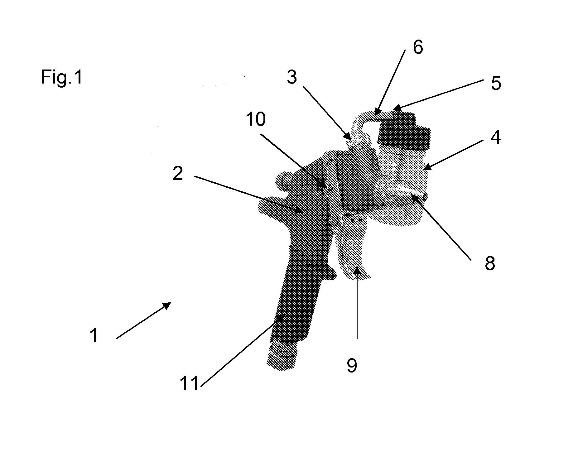
[0026]FIG. 1 illustrates a paint applicator suitable for inclusion in the device of this invention and to which the guiding means described hereinafter will be attached. This paint applicator or spraying gun (1) has a gun body (2) which includes a connecting region (3). This connecting region comprises a receiving bore (not shown) for removably attaching a paint receptacle, and a moveable cover (not shown) positioned at the lower end of said receiving bore. Herein the paint receptacle is depicted as comprising a gravity-feed container (4) which can be rotated about point (5) to initiate or stop flow of paint along the passage (6).

[0027]The cover is provided with a plastic or metal drip stop which serves to close the gravity feed container (4) when received in the receiving bore. Said cover is removably secured to the distal end of the passage (6) of the gravity feed container (4) with the aid of a thread or the like, said thread being connected to a trigger mechanism (9) which is pi...


PUM

PropertyMeasurementUnit
angleaaaaaaaaaa
angleaaaaaaaaaa
angleaaaaaaaaaa

Abstract

A device for applying paint, said device comprising a paint applicator (1) and a guiding means and being characterized in that said guiding means (23a, 23b) consists of two guiding rollers (23a, 23b), the axis of rotation of each roller being fixed in use such that the two axes are disposed at an angle to one another in the range from 50° to 130°. The device is particularly suitable for applying paint in a linear strip of predetermined width along architectural objects such as window sills and sashes, lintels and beams.

Description

FIELD OF THE INVENTION[0001]This invention relates to a device for applying a thin strip of a coating composition to a surface. More particularly this invention relates to a portable, hand-held device for applying a strip of a coating composition of predetermined width to a surface and which minimizes or prevents that composition from contacting or smearing unwanted portions of the surface.BACKGROUND OF THE INVENTION[0002]When applying a coating composition (e.g. paint) to particular structures such as window and picture frames, door panels and lintels, it is often desirable to prevent the coating from contacting areas adjacent to the structure. Painters will often outline the structure with masking tape or another protective coating so that minor inaccuracies in their brush strokes or spraying are prevented from reaching the underlying surface. This outlining process is obviously time-consuming. Furthermore, the removal of the protective tape or coating can leave behind remnants of...

Claims


Application Information

Patent Timeline
Patent Type & Authority Applications(United States)
IPC IPC(8): B43K8/00B05C5/00A46B5/00A46B13/00B05B15/68
CPCB05B7/2413B05C17/00589B05B15/08B05B7/2478B05B13/04B05B15/68
Inventor HOEK, AMERIKALBLAS, LENNOX J.DEN OUDEN, BERNARD J.
Owner AKZO NOBEL COATINGS INT BV
Why Eureka
Try Eureka