Check patentability & draft patents in minutes with Patsnap Eureka AI!

Thermoelectric tempering device

Inactive Publication Date: 2011-01-27
RITTALWERK RUDOLF LOH GMBH & CO KG
View PDF9 Cites 16 Cited by
  • Summary
  • Abstract
  • Description
  • Claims
  • Application Information

AI Technical Summary

Benefits of technology

These measures yield a compact design with a modular construction that can be easily expanded and adapted to different requirements. For example, the space-saving, compact design provides advantageous installation possibilities in an electrical cabinet containing built-in electronic components or also in smaller housings. Other uses are also possible, for example a cooling of surfaces or substances of various types. In addition to the compact, flat, and thus inexpensive design, a high efficiency and a low weight are achieved in comparison to conventionally designed devices. As known, the tempering can comprise a cooling or heating of the air conveyed past, depending on the selected electric current direction of the relevant tempering elements.
A compact design with a favorable degree of manageability is also facilitated if the housing insert is shortened in its longitudinal direction in comparison to the housing bottom part and if the controller is accommodated in the space between a narrow outside of the housing insert and the narrow inside of the housing bottom part oriented toward it.

Problems solved by technology

The overall ventilating device, together with the air flow chambers forms a relatively bulky unit.
It is difficult to achieve a definite air flow with this design.
Here, it is difficult to achieve definite flow ratios in the various possible installations.

Method used


Image

  • Thermoelectric tempering device
  • Thermoelectric tempering device
  • Thermoelectric tempering device

Examples


Embodiment Construction

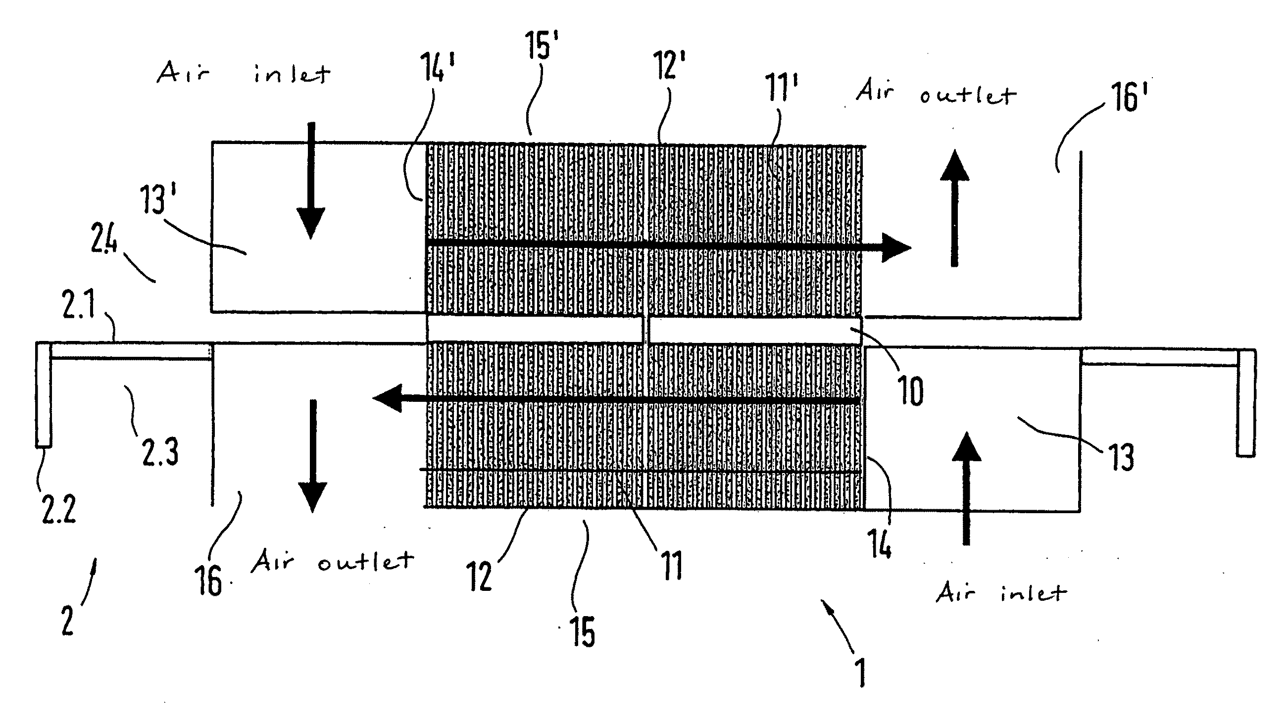
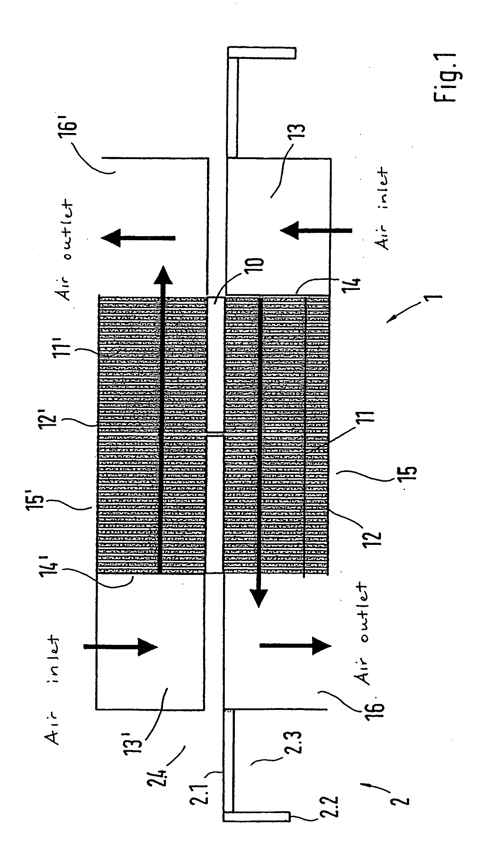
FIG. 1 shows a tempering module 1 of a thermoelectric tempering device, built into a rear wall 2.1 of an electrical cabinet 2. A part of the tempering module 1 is positioned or situated within the interior 2.3 of the electrical cabinet 2 delimited laterally by the side walls 2.2 while the other part is positioned or situated on the exterior 2.4 of the electrical cabinet 2. The part of the tempering module 1 oriented toward the interior 2.3 tempers the interior air of the electrical cabinet 2 in order, for example, to cool the interior air heated by the lost heat from electrical components and to maintain a particular temperature level. If the interior temperature is too low, the tempering module 1 can also be used to heat the interior air by reversing the flow direction. Similar built-in components of the tempering module 1 can also be provided in smaller interiors, such as in housings, and it is also possible for the tempering module 1 to be used in connection with surfaces to be c...


PUM


Abstract

A thermoelectric tempering device having a plurality of thermoelectrically operating tempering elements, including a cold surface, which forms upon the supply of an electric current, on one side thereof, and a warm surface on the opposite side thereof, including air / heat exchange bodies affixed on both sides and accommodated in a respective air flow chamber, and ventilators effecting an air flow along the same. Simple adjustment and expansion possibilities are provided with a unit of the tempering device configured as a tempering module and constructed so that the air flow chambers are configured as flow channels surrounding the heat exchange bodies parallel to the flow direction laterally and on the cover side facing away from the tempering elements, the flow channels having an air intake opening and an air discharge opening, wherein the ventilator of the respective flow channel is disposed on an intake opening or on a discharge opening.

Description

BACKGROUND OF THE INVENTION1. Field of the InventionThis invention relates to a thermoelectric tempering device having a plurality of thermoelectrically operating tempering elements, one side of which includes a cold surface that forms upon the supply of an electric current while an opposite side comprises a hot surface, and air / heat exchange elements are affixed to both sides, each accommodated in a respective air flow chamber, and ventilators produce an air flow along these air / heat exchange elements.2. Discussion of Related ArtA tempering device is disclosed in German Patent Reference DE 200 07 920 U1, in connection with a ventilating device for a housing, for example an electrical cabinet containing electronic equipment. This known ventilating device embodied as a roof unit is laid out as a flat, block-shaped unit equipped with a plurality of air flow chambers and among other things, has a heat exchange unit with at least one Peltier element that can cool or heat air flowing pas...

Claims


Application Information

Patent Timeline
IPC IPC(8): H01L35/30H05K7/20
CPCF24F5/0042F24F2221/36H01L35/32F28F2210/08H05K7/206H10N10/17
Inventor BRAUN, RALFBELL, LON E.DILLER, ROBERT W.REITZ, CHRISTOPH
Owner RITTALWERK RUDOLF LOH GMBH & CO KG
Features
  • R&D
  • Intellectual Property
  • Life Sciences
  • Materials
  • Tech Scout
  • Unparalleled Data Quality
  • Higher Quality Content
  • 60% Fewer Hallucinations
Learn More