
Apparatus and method for drilling fluid density separator utilizing rotating disks

a technology of density separator and rotating disk, which is applied in the direction of separation process, centrifuge, borehole/well accessories, etc., can solve the problems of coarser undesirable drill cuttings, high cost of minerals, and ineffective separation screen

Inactive Publication Date: 2011-01-27
NAT OILWELL VARCO LP
View PDF4 Cites 11 Cited by
  • Summary
  • Abstract
  • Description
  • Claims
  • Application Information

AI Technical Summary

Benefits of technology

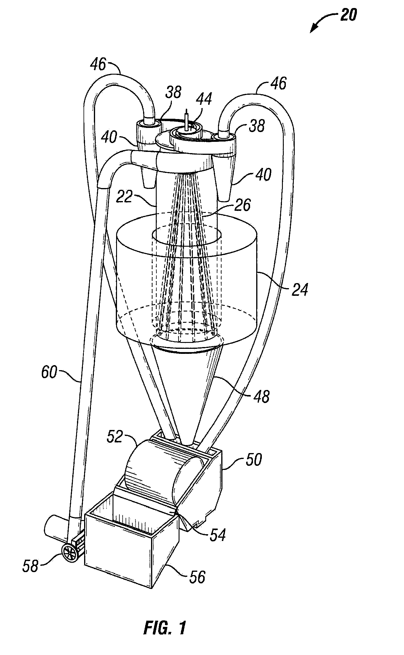
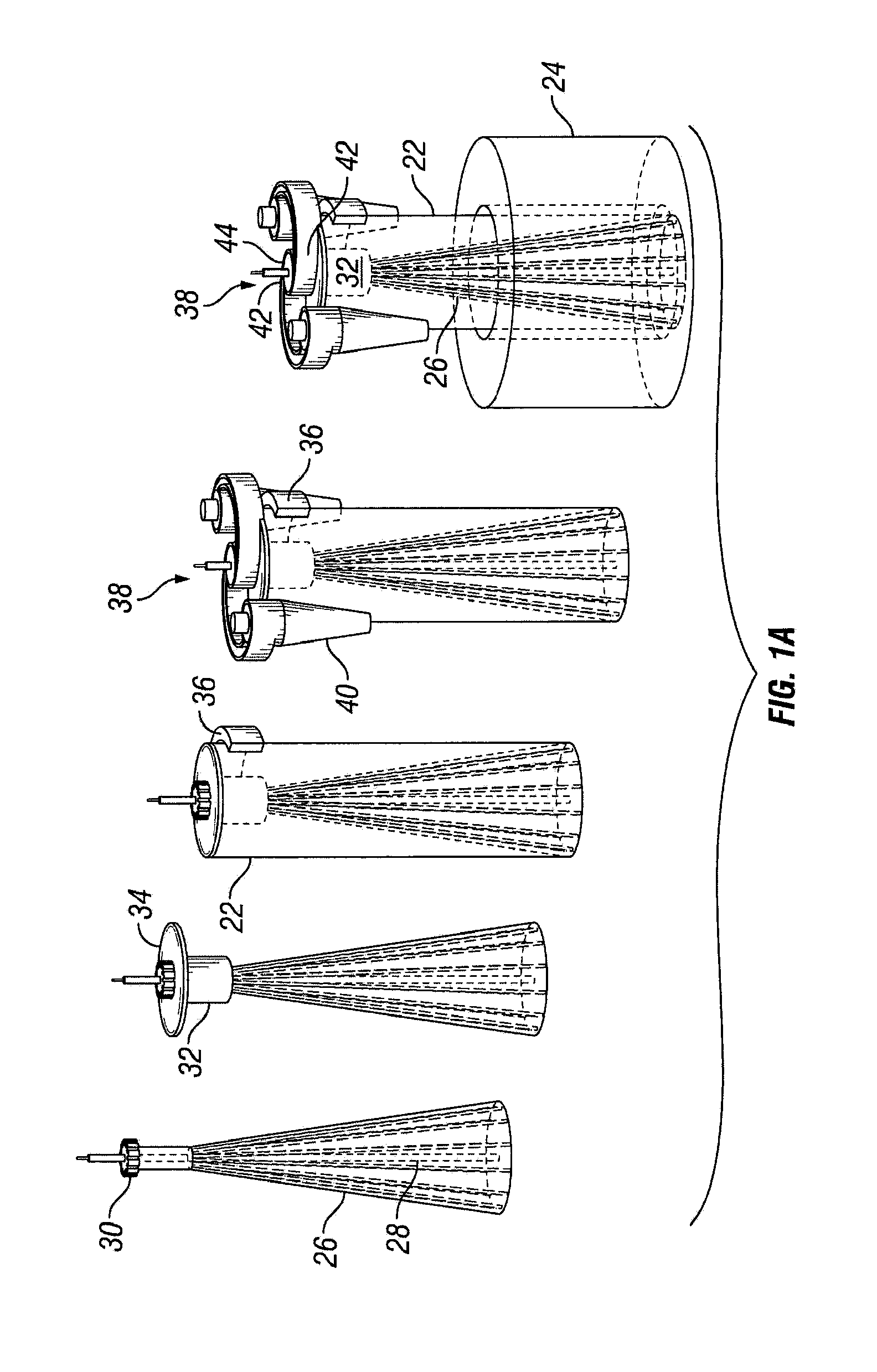
[0006]The present invention provides systems and methods to separate minerals based primarily on density, with only a minimal interference from the effect of particle size. In an exemplary embodiment, a separator creates and maintains slurry with a controllable density, which can be targeted between 3.0 and 3.9 kilograms per liter for separating barite from drill cuttings. The invention consists of a primary separation chamber containing the dense slurry, and a multiple number of secondary separation chambers used to separate cuttings from the d

Problems solved by technology

The barite and hematite are added to the mud in order to increase the fluid density, and these minerals are very expensive.
However, the disadvantage to such a method occurs when the sizes of the cuttings are substantially the same size as the barite or hematite.
As such, the screen is ineffective in isolating the barite or hematite.
However, the disadvantage to this method is that coarser undesirable drill cuttings also become pinned to the wall together with the dense minerals.

Method used


Image

  • Apparatus and method for drilling fluid density separator utilizing rotating disks
  • Apparatus and method for drilling fluid density separator utilizing rotating disks
  • Apparatus and method for drilling fluid density separator utilizing rotating disks

Examples


Embodiment Construction

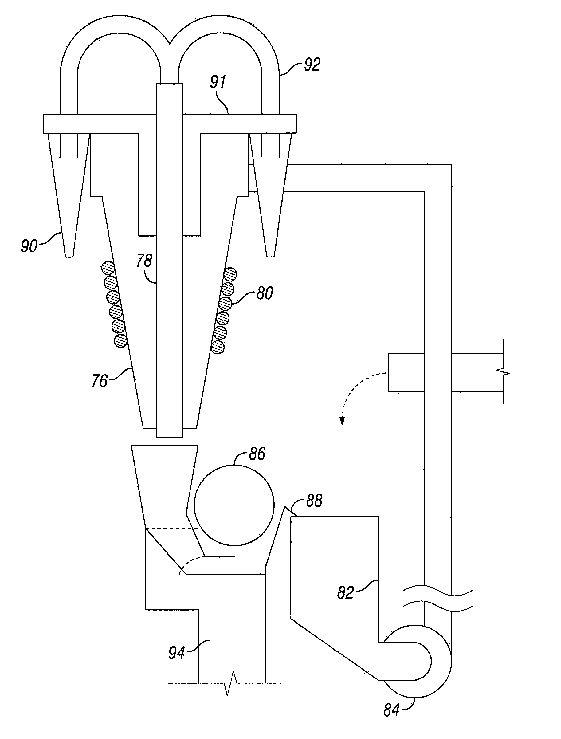
[0023]Illustrative embodiments of the invention are described below as they might be employed to separate and recover expensive drilling fluid additives. In the interest of clarity, not all features of an actual implementation are described in this specification. It will of course be appreciated that in the development of any such actual embodiment, numerous implementation-specific decisions must be made to achieve the developers' specific goals, such as compliance with system-related and business-related constraints, which will vary from one implementation to another. Moreover, it will be appreciated that such a development effort might be complex and time-consuming, but would nevertheless be a routine undertaking for those of ordinary skill in the art having the benefit of this disclosure. Further aspects and advantages of the various embodiments of the invention will become apparent from consideration of the following description and drawings.

[0024]FIG. 1 illustrates an exemplary...


PUM


Abstract

The present invention discloses a system for separating minerals in drilling fluid based primarily on density. The separator creates and maintains a slurry with a controllable density for separating minerals from drill cuttings. The density if controlled through the use of an electrode array. The separator comprises a primary separation chamber containing the dense slurry, and a multiple number of secondary separation chambers used to separate cuttings from the drilling fluid. The invention also contains inlet hardware allowing the mixed mineral suspension to enter the first separation chamber, and hardware allowing the three outlet (separated) streams to exit the device. One of the three outlet streams carries the minerals that have a density greater than the user selectable density set point, while the second carries the minerals that have a density less than the density set point, and the third carries clean drilling fluid.

Description

FIELD OF THE INVENTION[0001]The present invention relates generally to material separators, and specifically to a density separator for drilling fluid.BACKGROUND OF THE INVENTION[0002]Drilling mud has been utilized in hydrocarbon reservoirs for many years. The mud is used to establish a proper rate of penetration of the drill bit into the hole. Many variables, such as the desired hole depth, are considered when determining the necessary properties of the mud, and what materials are required to achieve the required consistency. The mud may include minerals called barite or hematite, both of which are very, dense. Other components in the mud may include a clay mineral that is intended to seal and lubricate the outside wall of the hole and create a specific rheology in the drilling mud.[0003]As the hole is drilled, drilling mud is constantly pumped down to the drill bit in order to clean the cuttings away from the bit. The mud then returns to the surface, carrying the drill cuttings wi...

Claims


Application Information

Patent Timeline
IPC IPC(8): B03C5/02
CPCE21B21/065B03C2201/18B03C1/32B03C5/02B03C1/02B03C1/30B01D21/26B03C1/023B03C1/0335B03C1/035E21B21/066
Inventor LARSON, THOMAS R.
Owner NAT OILWELL VARCO LP
Learn More