Electricity supply apparatus of an industrial site

a technology of electrical supply apparatus and industrial site, which is applied in the integration of power network operation system, transportation and packaging, energy industry, etc. it can solve the problems of disadvantageous damage to batteries, inability to maximize the energy storage efficiency of batteries, and inability to optimise battery usage. , to achieve the effect of optimizing battery usage, reducing current, and reducing the price per hour of electrical energy

Active Publication Date: 2011-01-27
TELECOM ITALIA SPA
View PDF15 Cites 33 Cited by
  • Summary
  • Abstract
  • Description
  • Claims
  • Application Information

AI Technical Summary

Benefits of technology

[0019]Accordingly, the Applicant has tackled the problem of providing an electricity supply apparatus of an industrial site (in particular, but not exclusively, a telecommunication site), which allows to minimize the amount of current drawn from the mains when the price per hour of the electrical energy is higher by using batteries, which batteries are then recharged when the price per hour of the electrical energy is lower, while optimising the batteries usage (in particular, by minimizing the risk of damaging the batteries and maximizing the energy storage efficiency of the batteries).

Problems solved by technology

The Applicant has noticed that the above solutions disadvantageously do not allow to optimise the batteries usage.
In particular, the above solutions disadvantageously could damage the batteries, since the conditions according to which discharge and recharge operations are performed (i.e. the recharge current, the discharge current, the minimum charge level and the maximum charge level) are determined only according to a peak shift function (in U.S. Pat. No. 6,885,115) or a function effectuating load-levelling during periods of peak demand on a utility (in U.S. Pat. No. 6,522,031).
In addition, the above solutions do not allow to maximize the energy storage efficiency of the batteries.

Method used


Image

  • Electricity supply apparatus of an industrial site
  • Electricity supply apparatus of an industrial site
  • Electricity supply apparatus of an industrial site

Examples


Embodiment Construction

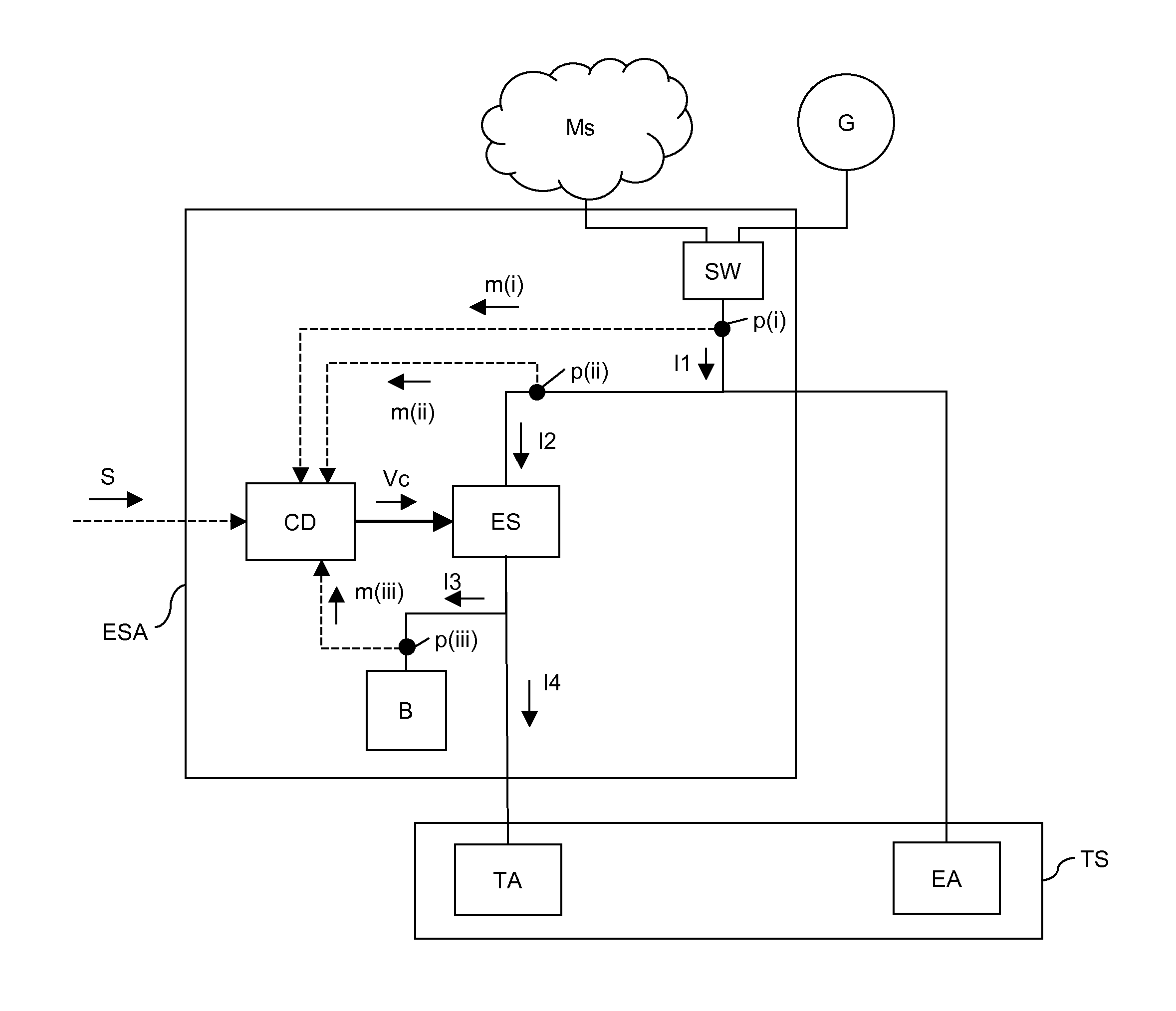
[0080]FIG. 1 schematically shows an electricity supply apparatus ESA for supplying electricity to an industrial site which comprises a load which requires to be supplied by an energy station.

[0081]By way of example, it is assumed that the industrial site is a telecommunication site TS comprising telecommunication apparatuses TA (i.e. the above load) and electrical apparatuses EA, in turn comprising auxiliary apparatuses which perform functions allowing the telecommunication apparatuses to operate and / or other electrical apparatuses (such as air conditioners and heating systems for the offices, elevators, computers, lightning system, etc.).

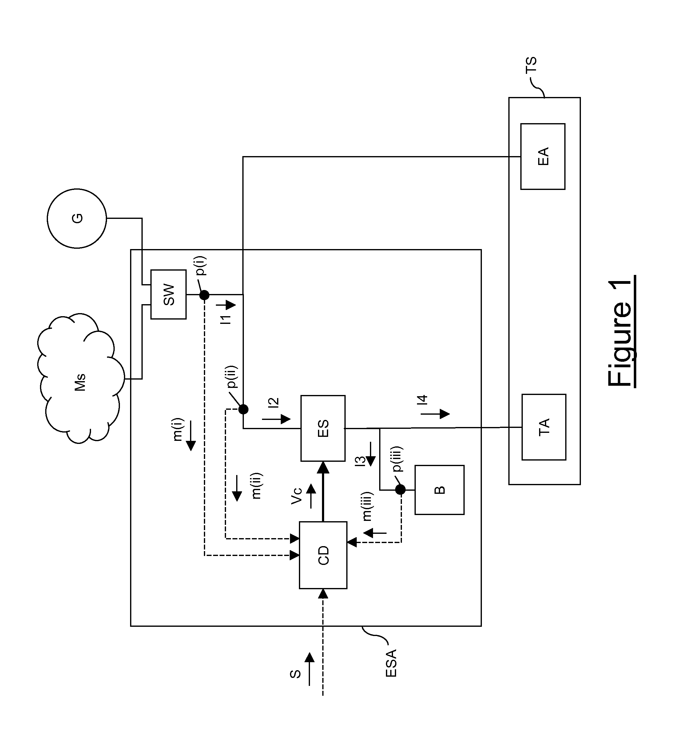
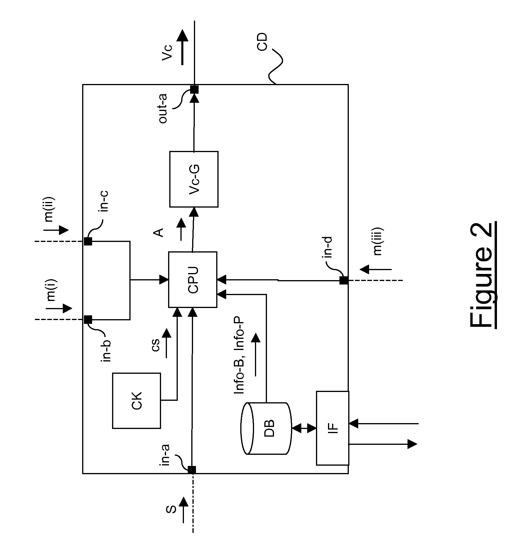
[0082]The electricity supply apparatus ESA preferably comprises a mains-generator switch SW, an energy station ES, a battery B, a control device CD and three probes p(i), p(ii) and p(iii). Even though FIG. 1 only shows a single battery B, the apparatus ESA may comprise any number of batteries, which are preferably connected the one to the other acc...


PUM


Abstract

An electricity supply apparatus includes a control device configured to calculate an amplitude of a control signal and to generate the control signal; an energy station configured to draw a current from a mains, to provide part of the drawn current to the load, to receive the control signal from the control device, and to vary the drawn current according to the amplitude; and a battery configured to recharge by drawing part of the drawn current and to discharge by supplying the load. The apparatus is characterized in that the control device is further configured to calculate the amplitude of the control signal also according to battery information relating to a recharge and / or a discharge condition of the battery.

Description

TECHNICAL FIELD[0001]The present invention relates to the field of electricity supply apparatuses. In particular, the present invention relates to an electricity supply apparatus of an industrial site, in particular (but not exclusively) a telecommunication site. Further, the present invention relates to a method for supplying such an industrial site.BACKGROUND ART[0002]A telecommunication network typically comprises a plurality of telecommunication sites distributed over the coverage area of the telecommunication network. Typically, each telecommunication site comprises a plurality of electrical and electronic apparatuses, such as:[0003]telecommunication apparatuses (e.g. switches, routers, etc.);[0004]auxiliary apparatuses which perform functions allowing the telecommunication apparatuses to operate (e.g. cable pressurizers, conditioners for keeping constant the temperature of the telecommunication apparatuses, etc.); and[0005]other electrical apparatuses (e.g. air conditioners an...

Claims


Application Information

Patent Timeline
Patent Type & Authority Applications(United States)
IPC IPC(8): H02J7/04
CPCH02J7/34H02J7/045Y02P80/10Y04S20/222Y02B70/3225H02J7/04H02J7/007182
Inventor BIANCIOTTO, ELIOBIANCO, CLAUDIOCUCCHIETTI, FLAVIOGRIFFA, GIANLUCA
Owner TELECOM ITALIA SPA
Why Eureka
Try Eureka