Method and device for determining the actuation position of an adjusting element of a motor vehicle
- Summary
- Abstract
- Description
- Claims
- Application Information
AI Technical Summary
Benefits of technology
Problems solved by technology
Method used
Image
Examples
Embodiment Construction
[0035]Corresponding parts are labeled with the same reference symbols in all figures.
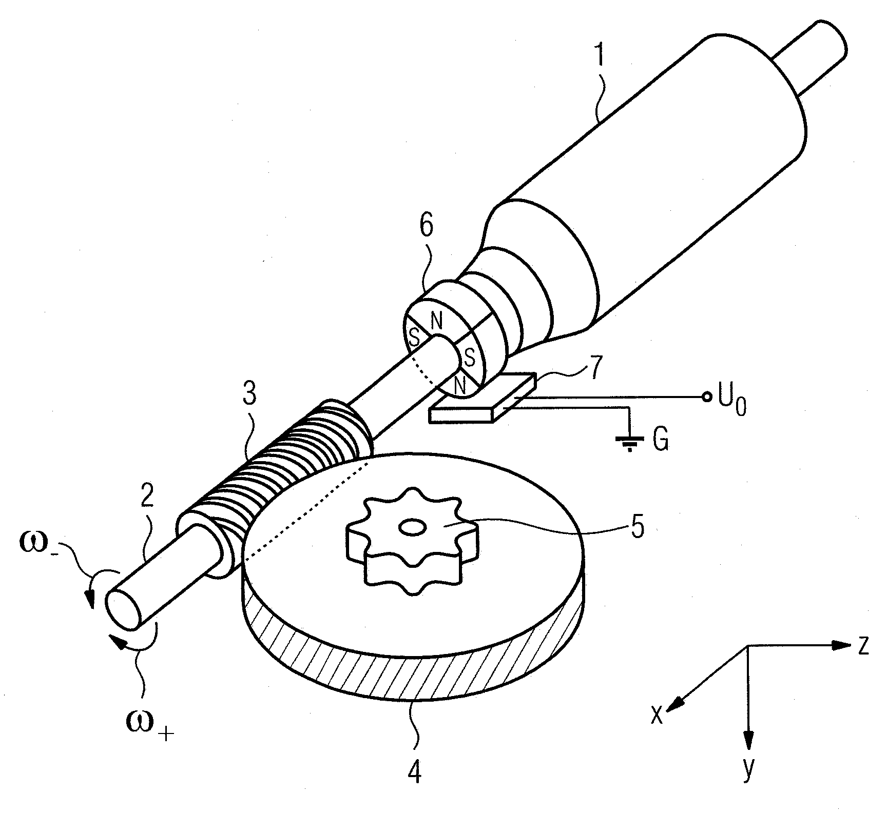
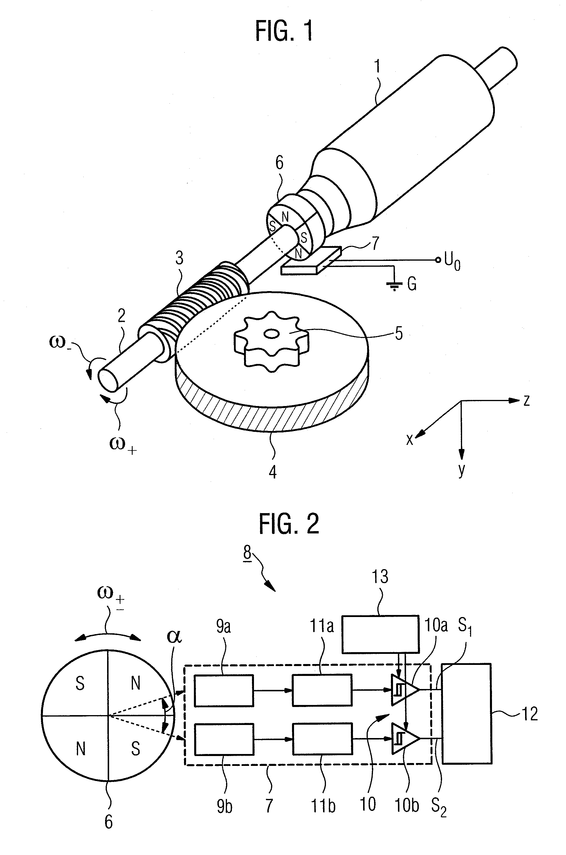
[0036]FIG. 1 shows an electric motor drive 1, for example a power window drive, of a motor vehicle with a drive shaft 2 bearing the rotor or armature (not shown) of an electric motor and with a worm drive that has a worm 3 located on the drive shaft 2 and a helical-cut worm gear 4 that meshes therewith. Due to the gear ratio between the worm 3 and the worm gear 4, the latter's rotational speed is reduced relative to the rotational speed ω of the drive shaft 2, while the torque is increased. While the drive shaft 2 rotates about the x axis shown, the worm gear 4, which lies in a plane parallel to the xz plane, rotates about an axis of rotation y that is perpendicular thereto.
[0037]The worm drive 3, 4 is mechanically coupled by means of a gear attachment 5 in a manner not shown in detail, for example a cable drum and a sheathed cable, to a carrier—often guided by rails—of a window as an adjusting elem...
PUM
 Abstract
Description
Claims
Application Information
 - R&D
- Intellectual Property
- Life Sciences
- Materials
- Tech Scout
- Unparalleled Data Quality
- Higher Quality Content
- 60% Fewer Hallucinations
Browse by: Latest US Patents, China's latest patents, Technical Efficacy Thesaurus, Application Domain, Technology Topic, Popular Technical Reports.
© 2025 PatSnap. All rights reserved.Legal|Privacy policy|Modern Slavery Act Transparency Statement|Sitemap|About US| Contact US: help@patsnap.com


