[0010]In the case of using encoded streams of such a long GOP configuration to perform editing
processing or the like, various types of
processing, e.g., color collection,
cut editing, or the like is performed as to image data obtained by decoding the encoded streams. Also, the image data after editing is encoded again to generate encoded streams. Thus, in the event of encoding and decoding being repeated, when the picture type differs from the last encoding, deterioration in image quality may become marked as compared to a case where the picture types are the same. For example, in the event of performing encoding so as to suppress deterioration in image quality of a reference picture by assigning great code amount to a reference picture to be referred from another picture, deterioration in image quality of the entire image can be reduced. Thus, when improving subjective image quality by providing image quality difference between a reference picture and a non-reference picture, in the event of a non-reference picture of which the image quality is inferior to the image quality of a reference picture being set to a reference picture at the next encoding, deterioration in image quality of the entire image increases.
[0011]Accordingly, it has been found to be desirable to provide an image encoding device and an image encoding method whereby deterioration in image quality can be reduced even when encoding and decoding of image data is repeated by employing a GOP configuration including reference pictures and non-reference pictures in a predetermined order.
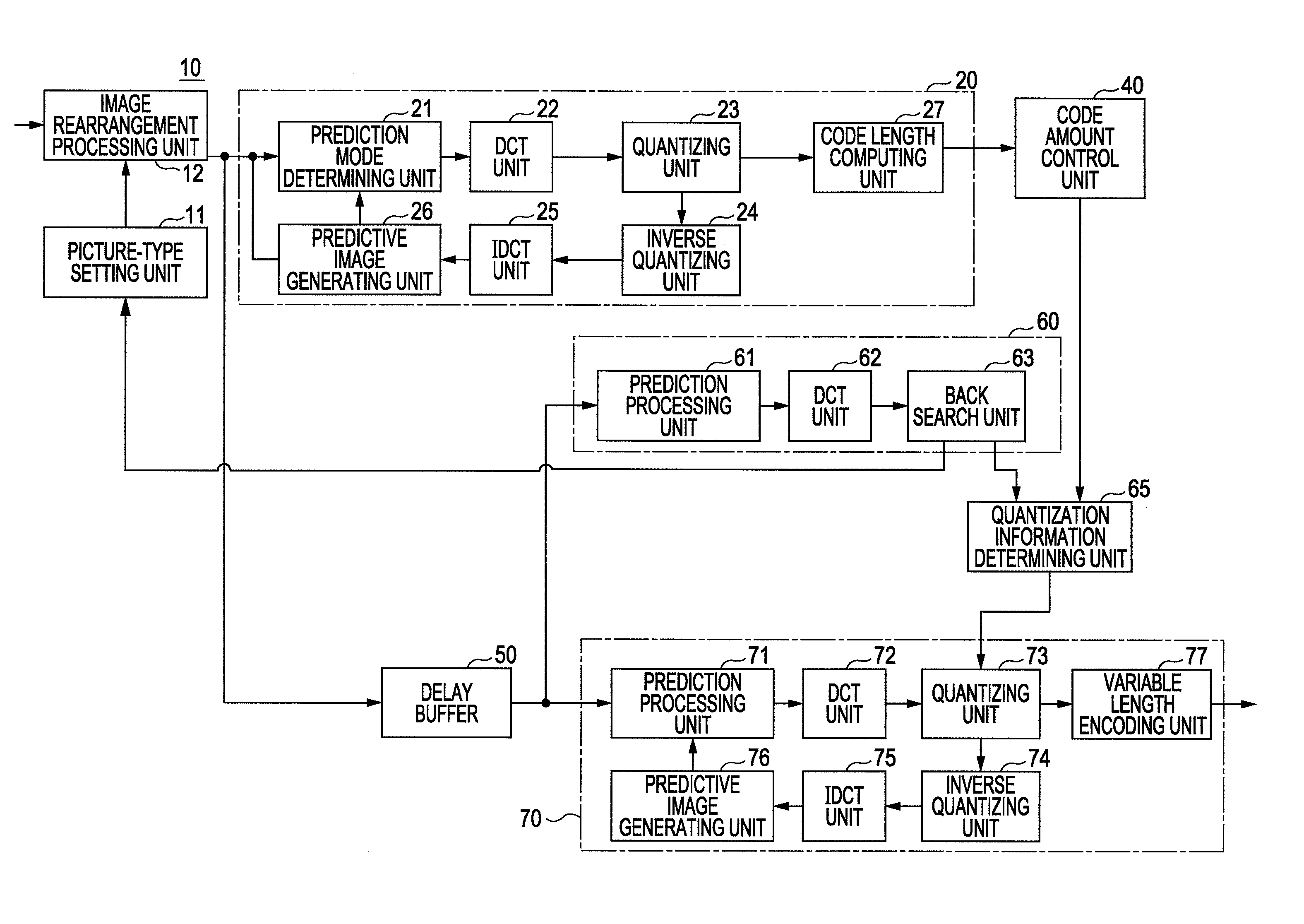
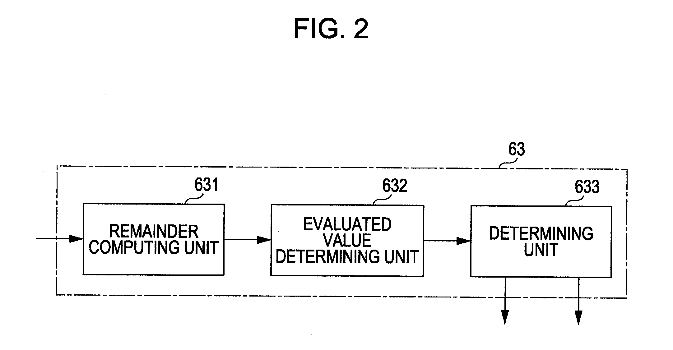
[0015]With the quantization information distinguishing unit, calculation of a
DCT coefficient is performed with the image of each frame of image data as an I picture, and quantization information that minimizes the summation of remainders, in increments of pictures, when performing division of the
DCT coefficient using quantization information is distinguished to be the quantization information used at the time of performing the last encoding. Here, the quantization information to be used for distinction is quantization information of a range with the quantization information set at the code amount
control unit as a reference, and accordingly, distinction does not have to be performed using all of the quantization information, and distinction of quantization information used at the time of performing the last encoding is facilitated.
[0016]With the picture-type setting unit, setting of a picture type is performed in increments of GOPs as to image data, and when the set picture type, and the picture type of which the quantization information has been distinguished at the quantization information distinguishing unit, differ, the picture types are matched by controlling the setting of the subsequent picture type. For example, the picture-type setting unit performs, at the time of the I picture distinguished at the quantization information distinguishing unit of which the phase advances as compared to the I picture to be set to the image data, adjustment of the length of GOP by reducing the number of pictures earlier than the I picture by the number of advancing pictures to match a picture type to be set to the image data, and a picture type at the time of performing the last encoding. Also, the picture-type setting unit performs, at the time of the I picture distinguished at the quantization information distinguishing unit of which the phase is lagging as compared to the I picture to be set to the image data, adjustment of the length of GOP by reducing the number of pictures of the next single or plurality of GOP to match the picture types of a reference picture and a non-reference picture to be set to the image data, and a picture type at the time of performing the last encoding. Such setting of a picture type is performed at the picture-type setting unit, and accordingly, the same picture type as that of the last encoding may be set to the image data.
[0018]Further, when a third encoding unit is provided to calculate a generated code amount by performing encoding for each of the quantization information with the image of each frame of the image data as an I picture using a plurality of different quantization information, the code amount
control unit performs prediction of quantization information that realizes a target generated code amount, and a generated code amount at the time of using this quantization information based on the generated code amount calculated at the first encoding unit, corrects the predicted generated code amount according to the generated code amount calculated at the third encoding unit, and performs setting of quantization information such that the generated code amount after correction realizes the target generated code amount. Thus, the quantization information realizing a target generated code amount can be distinguished with precision, and quantization information to be used for distinction of quantization information used at the time of performing the last encoding can accurately be selected.
[0020]Thus, deterioration in image quality can be reduced even when performing encoding and decoding of image data by employing a GOP configuration including a reference picture and a non-reference picture in a predetermined order.

