Simulated pressurized ball and manufacturing method

a technology of pressurized balls and manufacturing methods, applied in the field of balls, can solve the problems of air inside the ball contracting or expanding in cold and hot, users are unable to inflate the ball, and the outer textile layer or outer coating of the ball eventually wears away, so as to achieve the effect of resiliency, low weight, and boun

Active Publication Date: 2011-01-27
MCCARTHY KEVIN +1
View PDF16 Cites 8 Cited by
  • Summary
  • Abstract
  • Description
  • Claims
  • Application Information

AI Technical Summary

Benefits of technology

[0010]It is an object of the present invention to provide a non-pressurized sports ball that closely simulates the resiliency, bounce, hardness, and low weight of a pressurized sports ball.
[0011]It is another object of the present invention to provide such a sports ball that is not affected by ambient air pressure, temperature, and moisture and is more durable than a pressurized, inflatable sports ball.
[0012]It is a further object of the present invention to provide a relatively inexpensive method for manufacturing such a sports ball in different shapes and sizes.
[0013]These and other objects of the present invention are met by the sport ball and method of manufacturing disclosed herein. The sports ball is a light-weight, waterproof, non-pressurized, “breathable” structure and designed to simulate the resiliency, rebound, hardness and weight properties of a similar sized, pressurize, inflatable sports ball. The sports ball, which can be made in different sizes and shapes, is a hollow structure with a relatively thick sidewall made of specialized closed-cell foam, elastomeric resin. When cured, the sidewalls have sufficient compression and resiliency properties that enable the working action of the sidewall to use in place of air or an air bladder typically found in an inflatable sports ball. The sidewall is relatively thick and when the resin is cured, the ball is durable and resistant to normal wear and tear, water absorption and punctures.
[0015]Also disclosed herein a novel method of manufacturing a sports ball that allows the thickness of the sidewall to be adjusted to achieve the desired hardness and rebound properties found with different inflatable sports balls. During manufacturing, an undersized thermo-set injection mold is used whereby a reduce-scaled mandrel, which forms the ball's inner surface, is placed between two reduce-scaled cavity halves. When joined, the two halves form the ball's outer surface. An entry hole is formed on the side of the mold through which the support structure for the mandrel is extended. The entry hole is smaller than the spherical end of the mandrel. After curing, the two halves of the molds are quickly separated. The cross-linked expandable resin inside the mold then instantaneously expands, enlarging the finished ball to its full size. The ball and the entry hole in the ball have expanded such that the mandrel's larger spherical end is then easily removed. The expansion ratio of the ball, compared to the mold size is from about 1.4 to 1 up to 2.0 to 1.

Problems solved by technology

One drawback with inflatable balls is that the air inside the ball contracts or expands in cold and hot weather and in different elevations.
In some regions of the world however, where valve needles and air pumps are not available, users are unable to inflate the balls.
Another drawback with inflatable balls is that the outer textile layer or outer coating on the ball eventually wears away so that the air bladder is exposed.

Method used


Image

  • Simulated pressurized ball and manufacturing method
  • Simulated pressurized ball and manufacturing method
  • Simulated pressurized ball and manufacturing method

Examples


Embodiment Construction

)

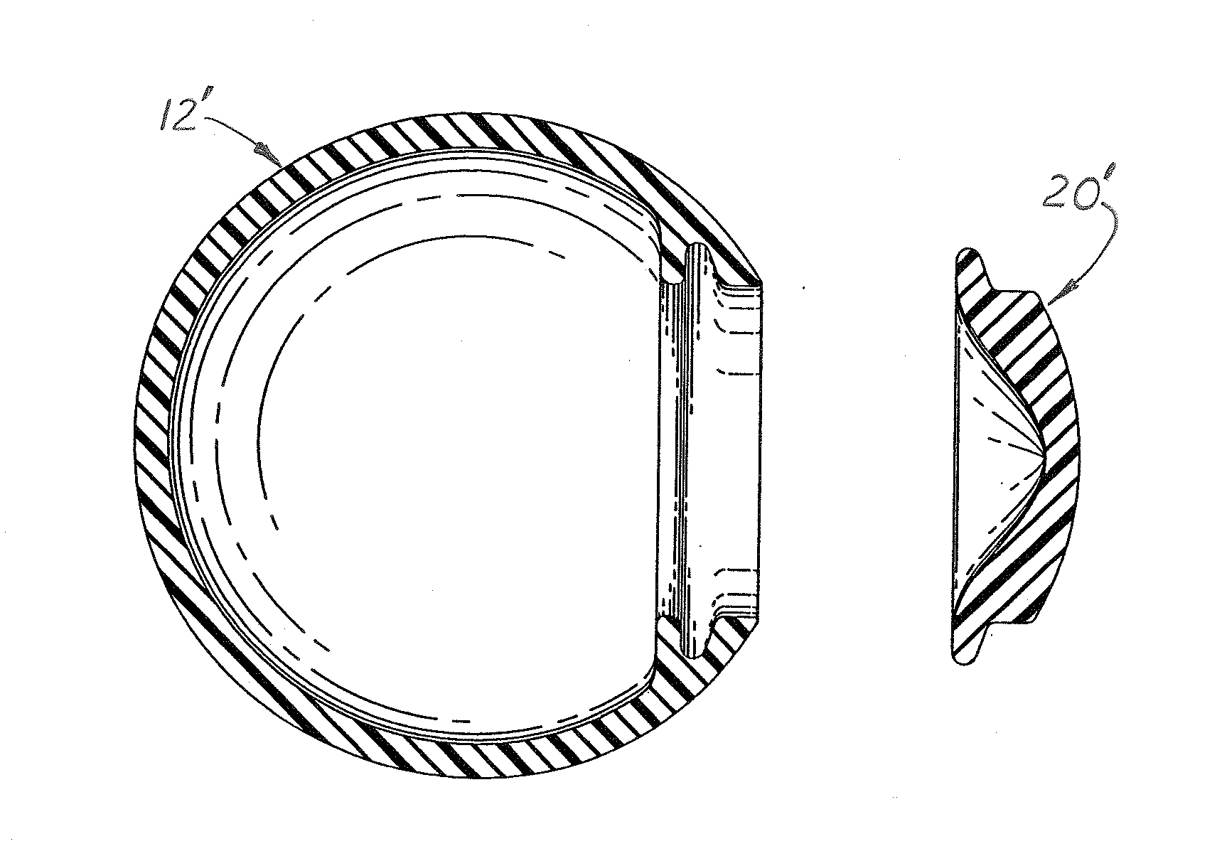
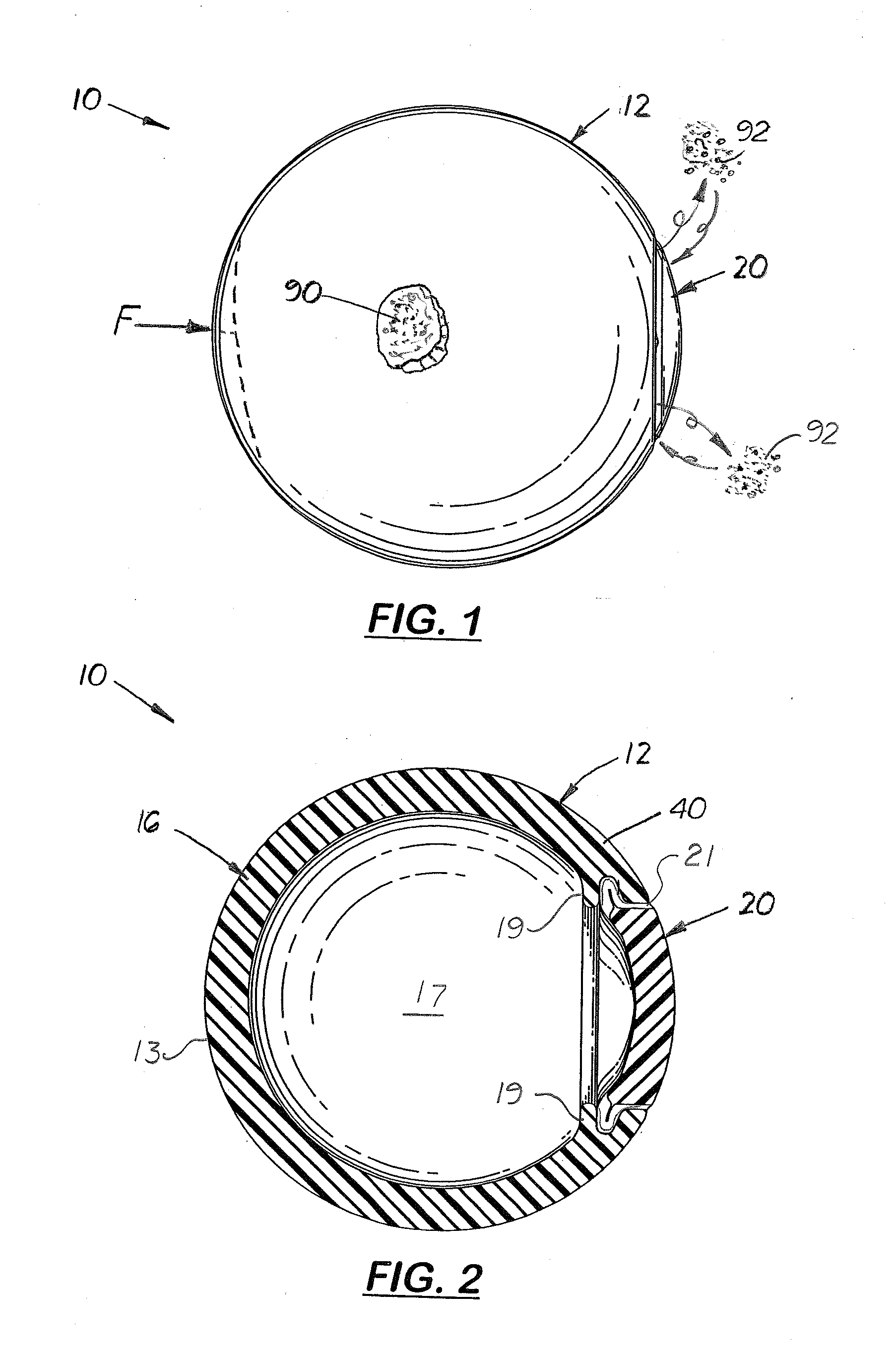
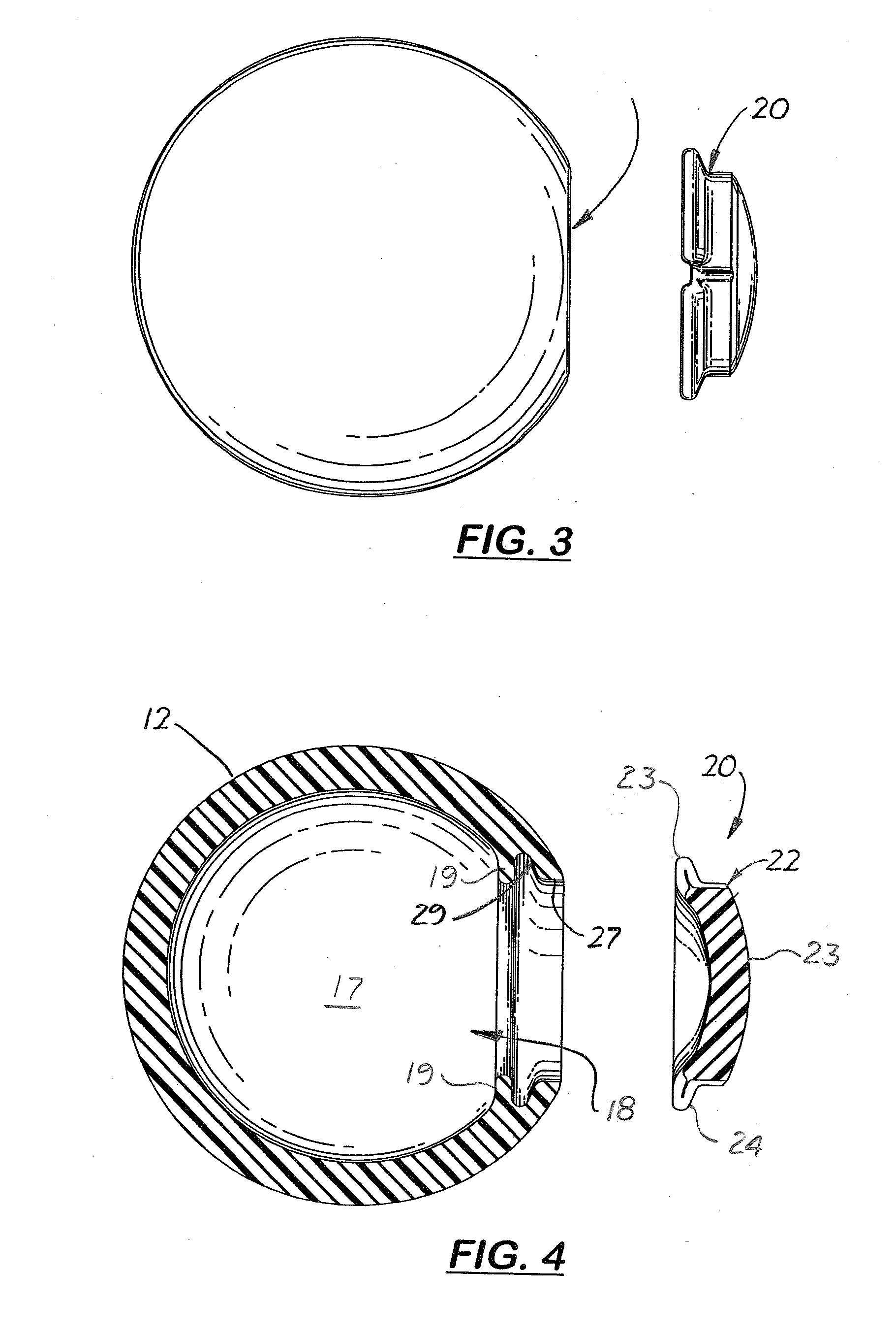
[0033]Referring to the accompanying FIGS. 1-17 there is shown a non-pressurized, non-inflatable structured sports ball 10 and designed to simulate the resiliency, rebound, hardness and weight properties of a similar sized, pressurize, inflatable sports ball. The sports ball 10 which can be made in different sizes and shapes, is a hollow structure with a relatively thick sidewall 20 made of closed-cell foam, elastomeric resin. When cured, the sidewall 40 has compression and resiliency properties that enable the working action of the sidewall 40 to be used in place of an air bladder commonly used in an inflatable sports ball. The sidewall 40 is relatively thicker than the sidewall found on a commonly used sports ball thereby making the ball 10 more durable and resistant to wear and tear and punctures. The sidewall 40 of the ball 10 forms a partially enclosed ball body 12 whereby both compression and tension forces on the sidewall 40 provide the working action on the ball rather than ...


PUM

PropertyMeasurementUnit
thicknessaaaaaaaaaa
thicknessaaaaaaaaaa
diameteraaaaaaaaaa

Abstract

A non-pressurized sport ball that simulates the resiliency, rebound, hardness and weight properties of a similar sized, inflatable sports ball. The sports ball, which can be made in different sizes and shapes, includes a hollow ball body with a relatively thick sidewall made of closed-cell foam, elastomeric resin. When cured, the sidewalls have compression and resiliency properties that enable the working action of the sidewall to be used in place of an air bladder in an inflatable sports ball. Formed on the ball body is an entry hole in which an air escaping cap is inserted made of the same elastomeric resin material as the ball body. During use, the cap flexes within the entry hole to allow air to exit and enter the ball during use so that the internal and external air pressures are equal. Also disclosed is a method of manufacturing the sports ball using a mandrel and a suitable-shaped compression mold with an entry hole formed on one side.

Description

[0001]This is a utility patent application which claims benefit of U.S. Provisional Application No. 61 / 228,128, filed on Jul. 23, 2009.[0002]Notice is hereby given that the following patent document contains original material which is subject to copyright protection. The copyright owner has no objection to the facsimile or digital download reproduction of all or part of the patent document, but otherwise reserves all copyrights whatsoever.BACKGROUND OF THE INVENTION[0003]1. Field of the Invention[0004]This invention pertains to balls that simulate pressured sports balls used for kicking, catching, and throwing and more particularly, to sports balls that maintain their uniform bounce and resiliency by an internal volume of air under different environmental conditions[0005]2. Description of the Related Art[0006]Many sports, such as soccer, football, rugby, volley ball, and basketball, require the use of an inflatable ball that have an inflated internal bladder or bag, generally made o...

Claims


Application Information

Patent Timeline
Patent Type & Authority Applications(United States)
IPC IPC(8): A63B39/02A63B45/00
CPCA63B39/00A63B45/00B29L2031/54B29C44/08A63B2039/003
Inventor MCCARTHY, KEVIN
Owner MCCARTHY KEVIN
Why Eureka
Try Eureka