Strainer, and snappy holding structure by the strainer

a holding structure and strainer technology, applied in the field of strainers, can solve the problems of small movement allowance of the switch lever in the up (contact) state, unstable positional attitude of the cam mechanism in contact/noncontact state, and prone to backlash of the cam mechanism, etc., to achieve no backlash, easy operation with small force, and simple structure

Inactive Publication Date: 2011-02-03
SAKAE RHYTHM MUSICAL INSTR
View PDF2 Cites 7 Cited by
  • Summary
  • Abstract
  • Description
  • Claims
  • Application Information

AI Technical Summary

Benefits of technology

With the strainer according to the present invention structure as described in the foregoing, with a simple structure attained by the operating lever and the link, the switch mechanism can be provided in a cost-effective manner. Further, when the operating lever is rotated upward, the snare assembly holding element can be lifted up in the direction substantially directly above by the link connected to the lever. Thus, being different from a conventional structure in which the element is pushed up diagonally upward by a linkage mechanism, the strainer according to the present invention can easily be operated with small force with no backlash occurring between the snare assembly holding element and the base element, and can maintain excellent operation feel. In a snare assembly contact state, even when the lever is inadvertently moved by a small amount, owing to its great allowance, a noncontact state is not easily be entered and the contact state can stably be maintained. Conversely, when the operating lever is rotated downward, the snare assembly holding element can be pushed down in the direction substantially directly underneath by the link. Thus, as being aided also by gravity, the snare assembly holding element smoothly goes down.
Further, it is structured such that the link is formed in an outwardly curved shape, and in accordance with an upward rotation operation of the operating lever, a connection point of the link at its other end to the operating lever moves past a dead point on a virtual line passing through a connection point of the link at its one end to the snare assembly holding element and a pivot point at the pedestal end side of the operating lever, to enter a base element central axis side, whereby a direction of repelling force received from the snare assembly via the link changes, attaining a stable attitude where the operating lever is unreturned. Therefore, in a snare assembly contact state, even when the operating lever is inadvertently touched during playing, the lever does not easily go down. Hence, the player can concentrate on playing the drum with no anxiety. Also, a great improvement is achieved in both the operation feel and stability when rotating the operating lever upward.
Still further, inside the base element, a guide groove is formed, the guide groove slidably guiding the snare assembly holding element in an engaged state in a vertical direction; an elastic member is protrusively formed inside the guide groove; and a vertically elongated concave groove that receives the elastic member so as to be relatively movable up and down is provided at a side surface of the snare assembly holding element facing the guide groove; wherein, as the operating lever is rotated upward to reach a position where the connection point aligns with the dead point, the elastic member abuts on a bottom end wall of the concave groove and deforms; in the stable attitude where the connection point is past the dead point, the elastic member abuts on the bottom end wall of the concave groove in a state wher

Problems solved by technology

However, such a cam mechanism is prone to suffer from backlash due to wear and the like caused by a concentrated load acting upon a portion around the cam aperture.
Further, the positional attitude of the cam mechanism in its contact/noncontact states is unstable because of its mechanism, and the movement allowance of the switch lever in its up (contact) state is small.
Hence, similarly to the above-described cam mechanism, it is prone to suffer from backlash which causes a reduction in operation feel.
Furthermore, again, because the force acts in the diagonal direction at the beginning of push-up, the force required for the operation is great, putting a burden upon the player.
However, such a mechanism poses problems of a very complicated structure and an increased burden on the snare assembly string because of the stretching rod directly abutting on the snare assembly string.
According

Method used


Image

  • Strainer, and snappy holding structure by the strainer
  • Strainer, and snappy holding structure by the strainer
  • Strainer, and snappy holding structure by the strainer

Examples


first embodiment

First, referring to FIGS. 1 to 9, a description will be given of the

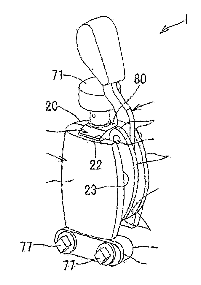
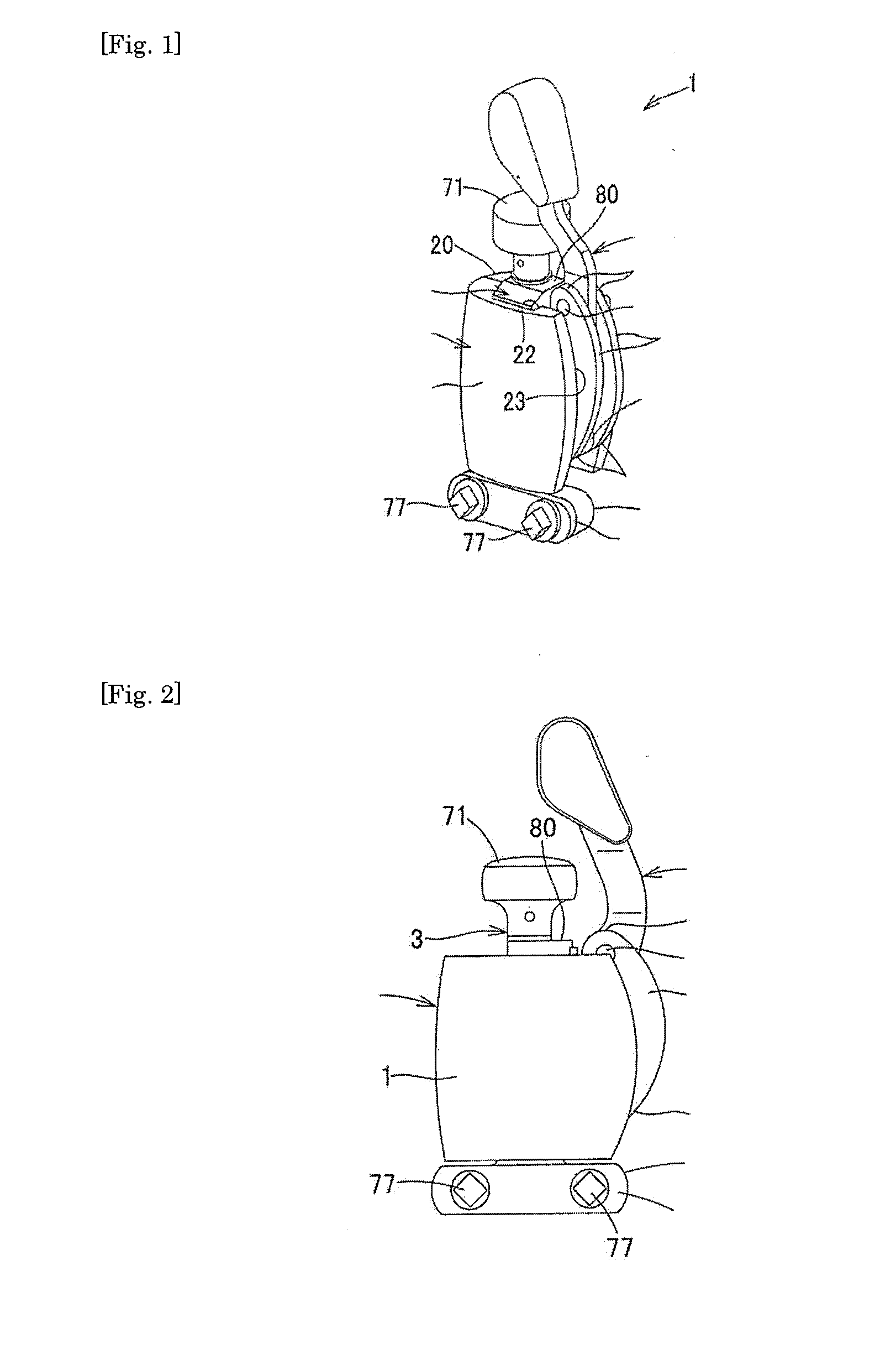
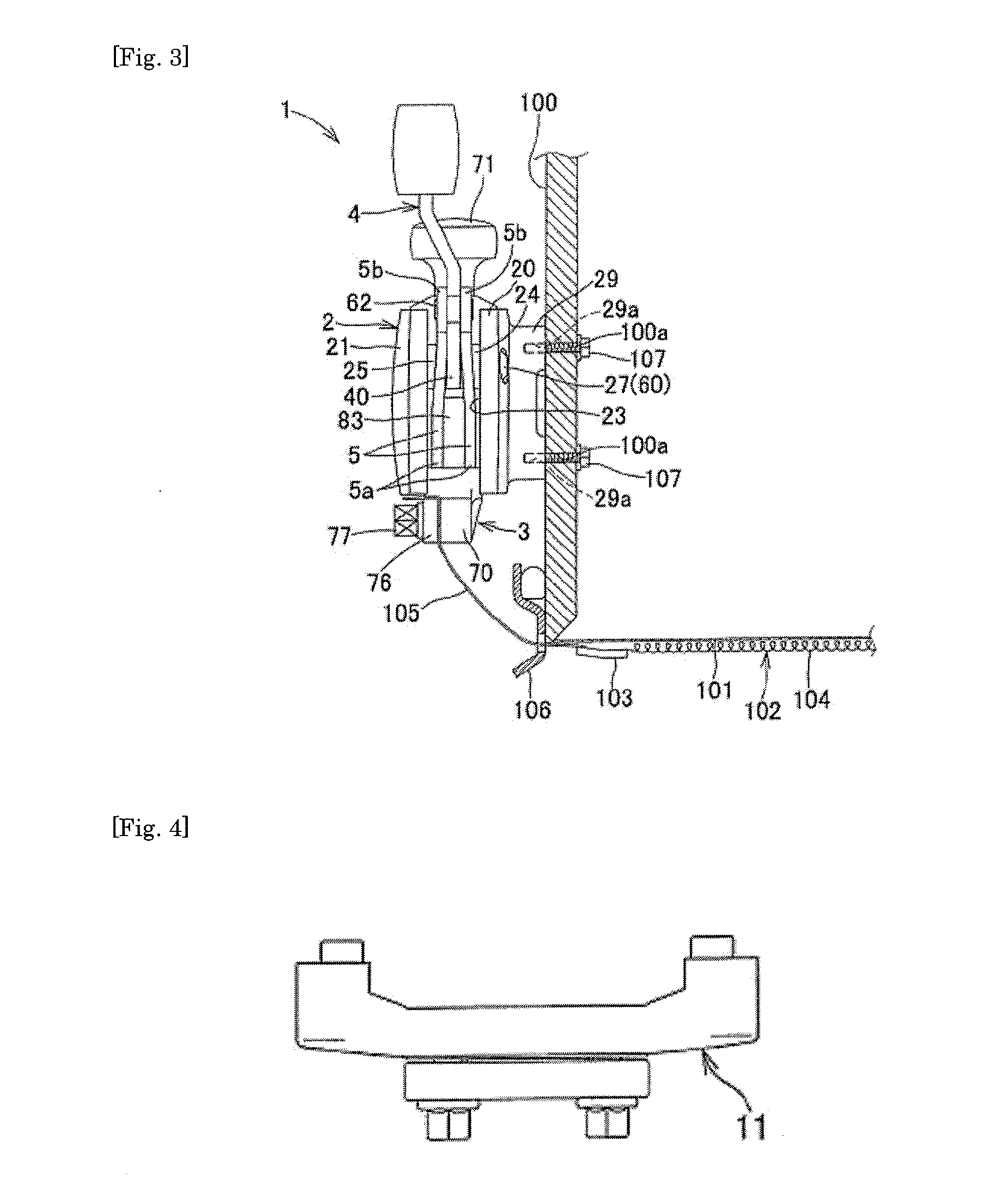
As shown in FIGS. 1 to 3, a strainer 1 includes a base element 2 that is fixed on a shell body 100 side of a drum; a snare assembly holding element 3 that is engaged with the base element 2 to freely slide up and down, and that has its bottom end side connected to a snare assembly 102; and an operating lever 4 that slides up and down the snare assembly holding element 3 relative to the base element 2, so as to switch the snare assembly 102 between contact / noncontact states relative to a drumhead 101.

As can also be seen from FIGS. 5 and 9, the present invention is characterized in further including a link 5 that pivotally and rotatably support a pedestal end of the operating lever 4 on the base element 2 via a shaft portion 60, the link 5 having its one end 5a rotatably connected to a site located lower than the shaft portion 60 of the operating lever 4 in the snare assembly holding element 3, and having its other en...

second embodiment

Next, referring to FIGS. 10 to 16, a description will be given of the

In connection with the second embodiment, the description will mainly be given of a snare assembly holding structure according to the present invention. FIG. 10 is a partial cross-sectional view showing a snare drum in which a snare assembly is held by a pair of strainers 1 and 11. In the drawing, the reference numeral 1 denotes a strainer equipped with a switch mechanism; 11 denotes a fixed type strainer; 100 denotes a drum shell body; 102 denotes a snare assembly; 105 denotes a snare assembly string at the snare assembly end; and St denotes a snare assembly holding structure. In the present embodiment, while the one strainer 1 is equipped with a switch mechanism and the other strainer 11 is of a fixed type, as in the conventional ones, both of the strainers may each be equipped with a switch mechanism. Further, in connection with the present embodiment, while the description will be given of an exemplary case whe...

third embodiment

Next, referring to FIGS. 18 to 22, a description will be given of the

The present embodiment is another embodiment of the strainer 1 equipped with a switch mechanism, wherein, as shown in FIG. 18, an elastic member 92 is protrusively formed toward the snare assembly holding element 3 inside the guide groove 22 that slidably guides the snare assembly holding element 3, and a vertically elongated concave groove 85 that receives the elastic member 92 so as to be relatively movable up and down is provided at a side surface of the snare assembly holding element 3 facing the guide groove 22. More specifically, as shown in FIGS. 20 and 21, a fit hole 90 into which the elastic member 92 is partially protrusively fit is formed at the bottom surface of the guide groove 22 on the split housing 20 side, and by a screw 93 that screws with a screw hole 91 formed at the fit hole 90, the elastic member 92 is fixed to the fit hole 90. Further, the concave groove 85 is formed at a side surface of the ...


PUM


Abstract

Intended is to provide a strainer having a switch mechanism, which is hardly rattled by a wear, which can be stably operated by a weak force, which does not load a snare assembly and which can maintain an excellent operation feel, and a snare assembly holding structure which has a reliable clamping force so that it can prevent the looseness of the snare assembly end portion. An operation lever is hinged on its base end side to a base body. A link is turnably connected on its one end side to the lower side portion of a snare assembly holding member, and is likewise turnably connected on its other end side to a midway position of the operation lever. When the operation lever turns upward, the snare assembly holding member is pulled upward through the link. When the operation lever turns downward, the snare assembly holding member is pushed downward.

Description

TECHNICAL FIELDThe present invention relates to a strainer for supporting a snare assembly end of a snare drum and for switching a snare assembly between contact / noncontact states relative to a drumhead, and a snare assembly holding structure with the strainer for supporting the snare assembly end on the drum shell body side.BACKGROUND ARTA snare drum is structured as follows: a top-side drumhead and a bottom-side drumhead are disposed to close both ends of a shell body, having hoops interposed therebetween, respectively. Further, a plurality of head adjustment devices for adjusting tension of the drumheads is disposed at an equal angular interval, so as to connect the top-side hoop and the bottom-side hoop. Strainers located in opposition at positions differing 180° at the shell body hold a snare assembly made up of a plurality of snare wires such that the snare assembly can be switched between a contact / noncontact state with respect to the bottom-side drumhead (for example, see Pa...

Claims


Application Information

Patent Timeline
IPC IPC(8): G10D13/02
CPCG10D13/025G10D13/02G10D13/18
Inventor NAKATA, EIZOMORIOKA, MANABUWARIISHI, TAKASHITSUJI, SHUNSAKU
Owner SAKAE RHYTHM MUSICAL INSTR
Why Eureka
Try Eureka