
Multi-stage switchable inertia track assembly

a switchable inertia track and multi-stage technology, applied in the direction of shock absorbers, drawing-off water installations, water supply installations, etc., can solve the problems of reducing the efficiency of the mount response, affecting the sealing effect of the valve, and difficult to seal from the low pressure side of the mount to the high or the high pressure side of the mount to the atmospher

Active Publication Date: 2011-02-03
CONTITECH USA INC
View PDF11 Cites 19 Cited by
  • Summary
  • Abstract
  • Description
  • Claims
  • Application Information

AI Technical Summary

Benefits of technology

[0010]A method of manufacturing a multistage switchable inertia track assembly includes providing a housing, positioning an inertia track in the housing that has an elongated fluid damped first path that is adapted to communicate with an associated first fluid chamber on a first side and an associated second fluid chamber on a second side, and a non-damped second path that is adapted to communicate with the associate...

Problems solved by technology

This external mounting tends to reduce the efficiency of the mount response, but it does allow for easier sealing of the hydraulic fluid in the mount assembly.
A problem with most conventional designs is that they use a diaphragm that encloses a volume and forms an air spring under the diaphragm and attached to an external port.
In either case, sealing of the valve can become an issue, where it is difficult to seal from either the low pressure side of the mount to high or from the high pressure side of the mount to atmosphere.

Method used


Image

  • Multi-stage switchable inertia track assembly
  • Multi-stage switchable inertia track assembly
  • Multi-stage switchable inertia track assembly

Examples


Embodiment Construction

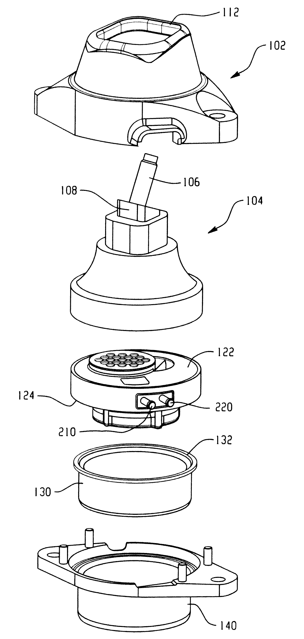
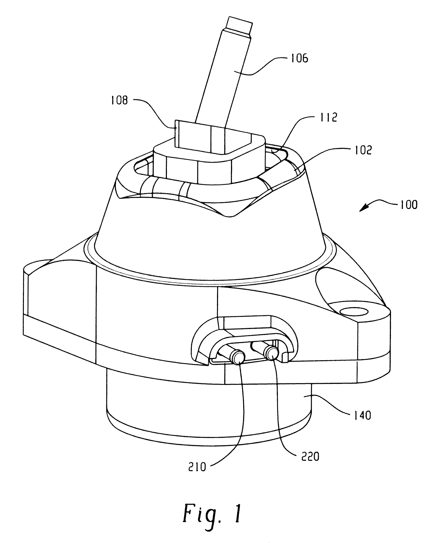
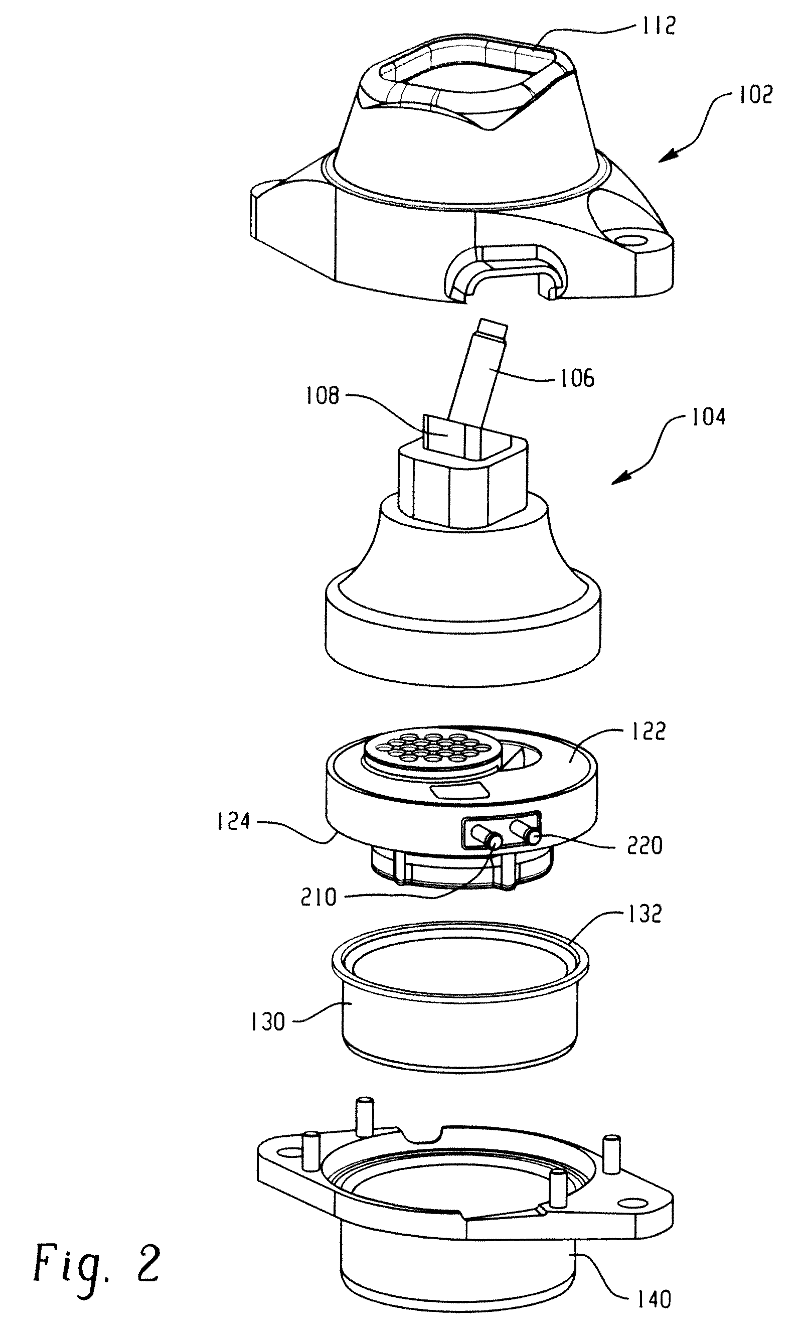
[0021]Turning first to FIGS. 1-3, a multi-state vacuum actuated inertia track assembly is shown within an engine mount or hydro-mount assembly 100. More particularly, the mount assembly 100 includes a restrictor or external housing 102 dimensioned to receive a first or elastomeric component or main rubber element 104 that is generally shaped as a truncated cone, and primarily made of an elastomeric material, such as an elastic rubber as is conventional in the art. A fastener or bolt 106 extends outwardly from the main rubber element for fastening to the power train or engine (not shown) in a manner generally known in the art. The fastener cooperates with a metal bearing member 108 that has at least a portion encapsulated within the first elastomeric member 104. In addition, a lower peripheral portion of the main rubber element may include a stiffener, such as metallic stiffener 110, molded within the main rubber element to add rigidity and support.

[0022]The main rubber element is re...


PUM

PropertyMeasurementUnit
Lengthaaaaaaaaaa
Pressureaaaaaaaaaa
Dimensionaaaaaaaaaa

Abstract

A two vacuum actuated switch mechanism is provided within an engine or hydromount. First and second ports are provided along a peripheral portion of an inertia track assembly. A decoupler or vacuum diaphragm is selectively exposed to vacuum through a first port. Under the influence of the vacuum, the decoupler can no longer oscillate. If vacuum is applied only to the decoupler, and not and idle diaphragm, the fluid is forced through a low frequency inertia track which creates high levels of damping and low frequencies. If vacuum is also applied to the decoupler and the idle diaphragm, the high frequency inertia track is opened and causes the fluid to flow therethrough. This creates a high frequency dynamic rate dip. Alternatively, if no vacuum is applied to either the decoupler or the idle diaphragm, the decoupler is allowed to freely oscillate creating a decoupled state for low input displacements. Higher input displacements results in fluids being forced through the low frequency inertia track. An integrated accumulator is disposed between the port and the decoupler to reduce or eliminate air resonance response, buffering the pumping effect of the decoupler in a decoupled state.

Description

BACKGROUND OF THE DISCLOSURE[0001]This application is a continuation-in-part application and claims priority from PCT / US2009 / 034907, filed 23 Feb. 2009, which claims priority from U.S. provisional patent application Ser. No. 61 / 030,360, filed 21 Feb. 2008, the disclosures of which are hereby expressly incorporated herein by reference.[0002]This disclosure relates to a damper assembly and specifically a multi-stage switchable inertia track assembly. More particularly, the multi-stage switchable inertia track assembly contains both a low frequency inertia track and a high frequency inertia track. The low frequency track is used to create damping to address vehicle smooth road shake. The high frequency track is used to create a high frequency sympathetic resonance to reduce transmission of idle disturbance frequencies from the powertrain to a vehicle body or frame. Selected features may find application in other related environments and applications.[0003]The basic technology for switc...

Claims


Application Information

Patent Timeline
IPC IPC(8): F16F13/28F16F9/50F16F9/504F16F9/02B23P11/00
CPCF16F13/262Y10T137/0402
Inventor BRADSHAW, JEFFHARTGERS, ANDREW
Owner CONTITECH USA INC
Learn More