Universal system for charging at least one portable device

a portable device and universal technology, applied in the direction of mobile unit charging stations, electric vehicles, safety/protection battery circuits, etc., can solve the problems of significant financial consequences for companies, low added value of chargers, and negative impact on the image of generally well-known brands under which appliances are sold

Inactive Publication Date: 2011-02-03
ERGYLINK
View PDF14 Cites 78 Cited by
  • Summary
  • Abstract
  • Description
  • Claims
  • Application Information

AI Technical Summary

Benefits of technology

[0050]This concerns said device and / or said adapter and mainly meets needs for convenience and / or of an aesthetic order. The cable length to be concealed may for example more particularly concern said device if this is a cable for connection with an external energy source. The cable length to be concealed may also concern at least one cable within the scope of said at least one adapter for either one or both interfaces for connection with the device or with said at least one portable appliance. It is further provided that the technical means for concealing at least one excess cable length may be based on winders. These may be so-called automatic winders by the use of a spring for exerting a force allowing the cable to be wound up or further simple winders, i.e. means with which the user may himself / herself wind up the excess length. Solutions for concealing excess cable length based on suitable housings are also provided. This may for example be a retention housing provided between the point for connecting the relevant cable and the exit point of the cable from the outer casing of the relevant object. Thus, with a simple exit point allowing the cable to slide freely, it is possible to have the excess portion of the cable enter the retention housing. Generally it is sufficient to pull on the cable, one portion of which has been concealed beforehand in the housing, in order to extend the external portion. When said housing is common for retaining the excess portion of several cables, it is advantageous to provide an access for disentangling their excess portion if necessary. For all the types of winders or solutions based on a housing for containing the excess portion of at least one cable, by applying blocking means, it is advantageously possible to maintain the wound portion in place without it unwinding by itself and to maintain free of any return force the length of the terminal portion which the user has chosen to leave free.
[0122]This is the possibility of recharging, with the system according to the invention, portable appliances for which the voltage supply for recharging is lower than that provided by the retained connector for the end of the cable of the adapter according to the invention. The intention is to use the voltage drop at the terminals of a diode which is a characteristic which is relatively independent of the current flowing through it, in order to be able to produce an inexpensive, not very bulky voltage step-down device and which is further easily integrable into a component made by overmoulding without requiring any printed circuit. By selecting diodes in suitable categories, the intention is to be able to determine the output voltage of the step-down device in a relatively fine way from a known input voltage. For example, by using conventional silicon diodes mounted in series, the input voltage is lowered by 0.6V per diode. By including so-called Schottky diodes in the series circuit, it is possible to finely adjust the output voltage by a drop of 0.2V per diode. In practice, it is sufficient to use 1A silicon diodes of general use, for example from the <<1N4000>> series which are particularly economical and robust in order to obtain an output voltage which is comprised within the tolerance of the portable appliance to be powered.

Problems solved by technology

Indeed, the chargers are not very technological objects with low added value, and without any marketing issue for manufacturers of portable electronic appliances.
The risks in the case of dysfunction of the chargers may have significant financial consequences for the companies and a negative impact on the image of the generally well-known brands under which the appliances are sold.

Method used


Image

  • Universal system for charging at least one portable device
  • Universal system for charging at least one portable device
  • Universal system for charging at least one portable device

Examples


first embodiment

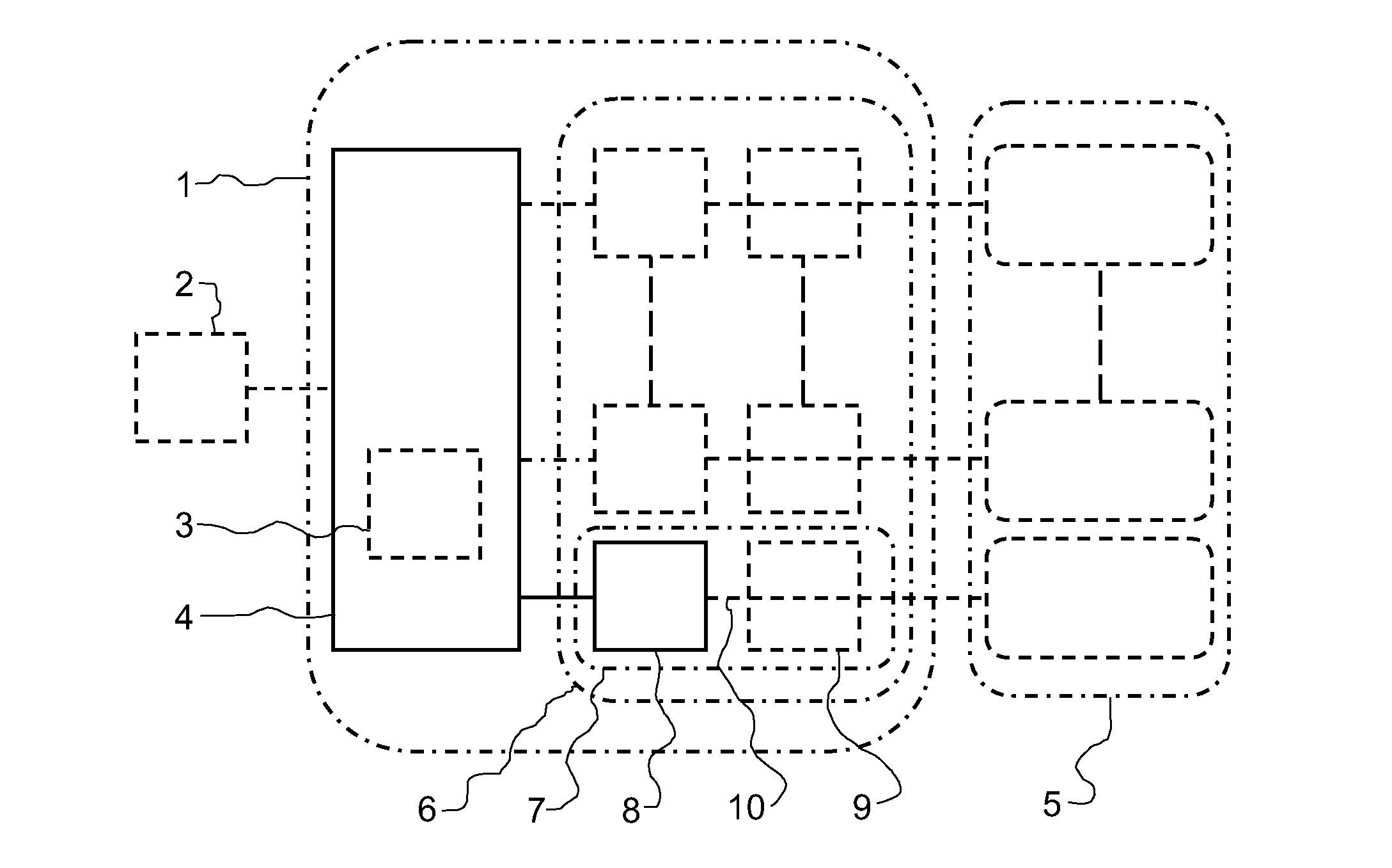
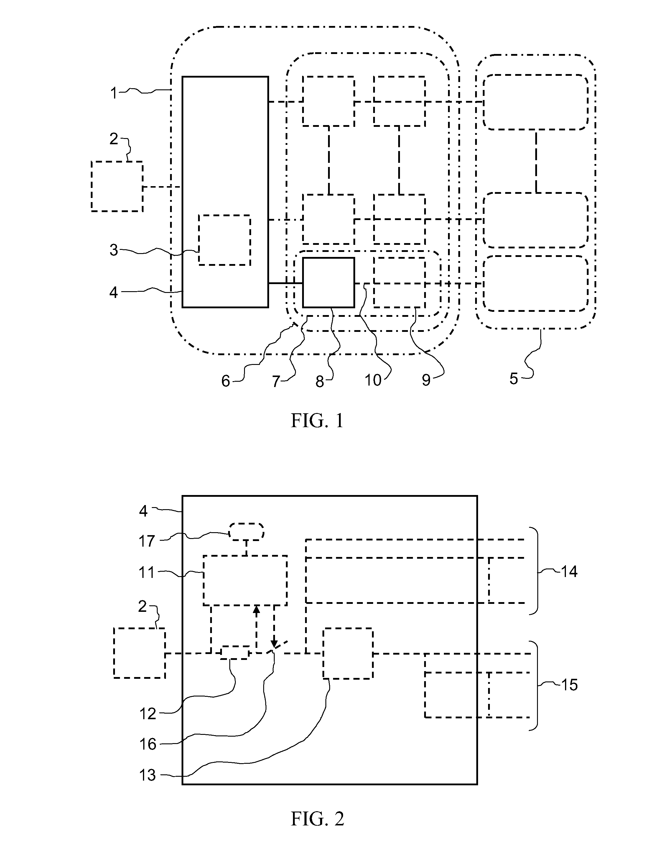
[0167]FIG. 26 illustrates the system according to the invention allowing recharging of a plurality of portable appliances of distinct designs or totally or partly identical. The recharging is carried out at least simultaneously for part of the appliances. Indeed, according to a refinement of the invention, when the maximum power capabilities of the power supply source of the device are reached, the charging of the appliances remaining to be recharged is carried out in a sequential mode. This example illustrates an alternative comprising several locations with different sizes for covering most of the needs without however maximizing the size of each location so as to allow all of them to receive more bulky appliances. Adjustable guiding means 261 allow adaptation of the width of the recharging locations to that of the portable appliances, other means such as for example a blade of flexible material forming a spring allow adaptation of each location to the thickness of the appliance. ...

second embodiment

[0168]FIG. 27 illustrates this system which differs from that of FIG. 26 by an orientation of the recharging locations which is perpendicular to the main axis of the device. In this example, the recharging locations all have the same maximum width and are equipped with an indicator 271 for indicating their functional condition. In this alternative, the guiding means which are adjustable depending on at least the width of each portable appliance do not exert any pressure on the appliance. It is provided that in certain sophisticated alternatives, electrically controllable means for maintaining the appliance at the bottom of its location during recharging release the appliance when charging is considered as having ended.

third embodiment

[0169]FIG. 28 illustrates the system which differs from that of FIG. 27 by one of the recharging locations comprising a system for adaptation to the dimensions of the portable appliances which does not require any adjustment from the user. Means 281 exerting pressure in the direction opposite to their attachment face automatically place the portable appliance in the recharging position when it is inserted. By the combined effect of the forces exerted by the automatic positioning means and of the frictional forces of these means on the second sub-assembly and / or on the portable appliance, the appliances are maintained safely in the recharging position. This feature makes this alternative particularly advantageous for vehicle uses. This exemplary embodiment further illustrates the case of a self-contained energy source 282 comprised in the device. Thus, after prior charging of the self-contained source by connecting the device to an external energy source during the required time, the...


PUM


Abstract

A universal system for recharging at least one portable appliance, the dedication of which is being capable from a device (4) of suiting any portable appliance version by means of at least one adapter (6) which may be specific in all or part of the relevant portable appliance. The invention, in its preferred alternative embodiments, allows simultaneous or sequential recharging of a plurality of portable appliances. With the invention it is further possible to save electric energy in a stand-by mode and the risks of fire and electrocution in the case of any dysfunction are reduced as compared with the solutions of the state of the art.

Description

TECHNICAL FIELD[0001]The present invention is located in the field of small electrical equipment, it relates to an accessory for recharging at least one portable device. The invention more particularly relates to recharging telephones and / or other portable electrical or electronic appliances of daily use.STATE OF THE PRIOR ART[0002]The chargers of the state of the art are most often specific accessories provided by the manufacturers of portable devices. Although there is work aiming at standardizing the interface between the chargers and the devices to be recharged for decoupling the provision of devices and chargers, the pool of existing chargers is still heterogeneous. This heterogeneity forces the users to keep and carry in their travels as many chargers as there are appliances to be recharged. On the other hand, in families where most of the members have a simple or multifunctional portable telephone and if necessary, other portable appliances such as digital audio readers, digi...

Claims


Application Information

Patent Timeline
Patent Type & Authority Applications(United States)
IPC IPC(8): H02J7/00
CPCH02J7/0027H02J7/0044H02J7/025H02J7/0026H02J7/0072H02J7/0013H02J2310/22H02J7/00712H02J50/10
Inventor GILBERT, JEROME
Owner ERGYLINK
Why Eureka
Try Eureka