

Imaging device and optical axis control method
a technology of optical axis control and imaging device, which is applied in the direction of exposure control, instruments, television systems, etc., can solve the problems of thin imaging device, large device size, and difficult to obtain a small siz
- Summary
- Abstract
- Description
- Claims
- Application Information
AI Technical Summary
Benefits of technology
Problems solved by technology
Method used
Image

Examples
first embodiment
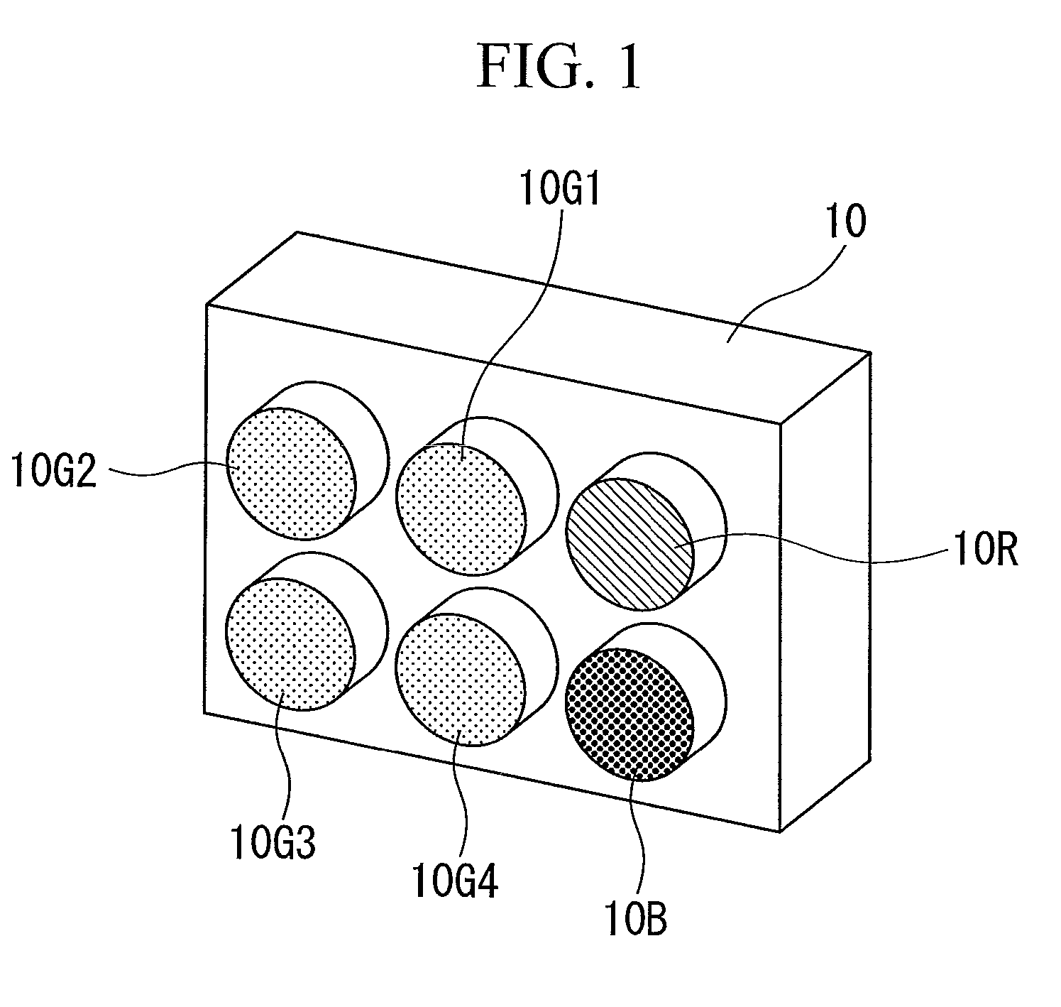
[0057]Hereinafter, an imaging device according to a first embodiment of the present invention will be described with reference to the accompanying drawings. FIG. 1 shows an appearance of the imaging device in the first embodiment. As shown in FIG. 1, in the imaging device according to the present invention, six-channel image pickup units are fixed to a substrate 10. The six-channel image pickup units include four-channel green image pickup units 10G1, 10G2, 10G3, and 10G4, a one-channel red image pickup unit 10R, and a one-channel blue image pickup unit 10B. The four-channel green image pickup units 10G1, 10G2, 10G3, and 10G4 each includes a color filter which transmits green light. The one-channel red image pickup unit 10R includes a color filter which transmits red light. The one-channel blue image pickup unit 10B includes a color filter which transmits blue light.
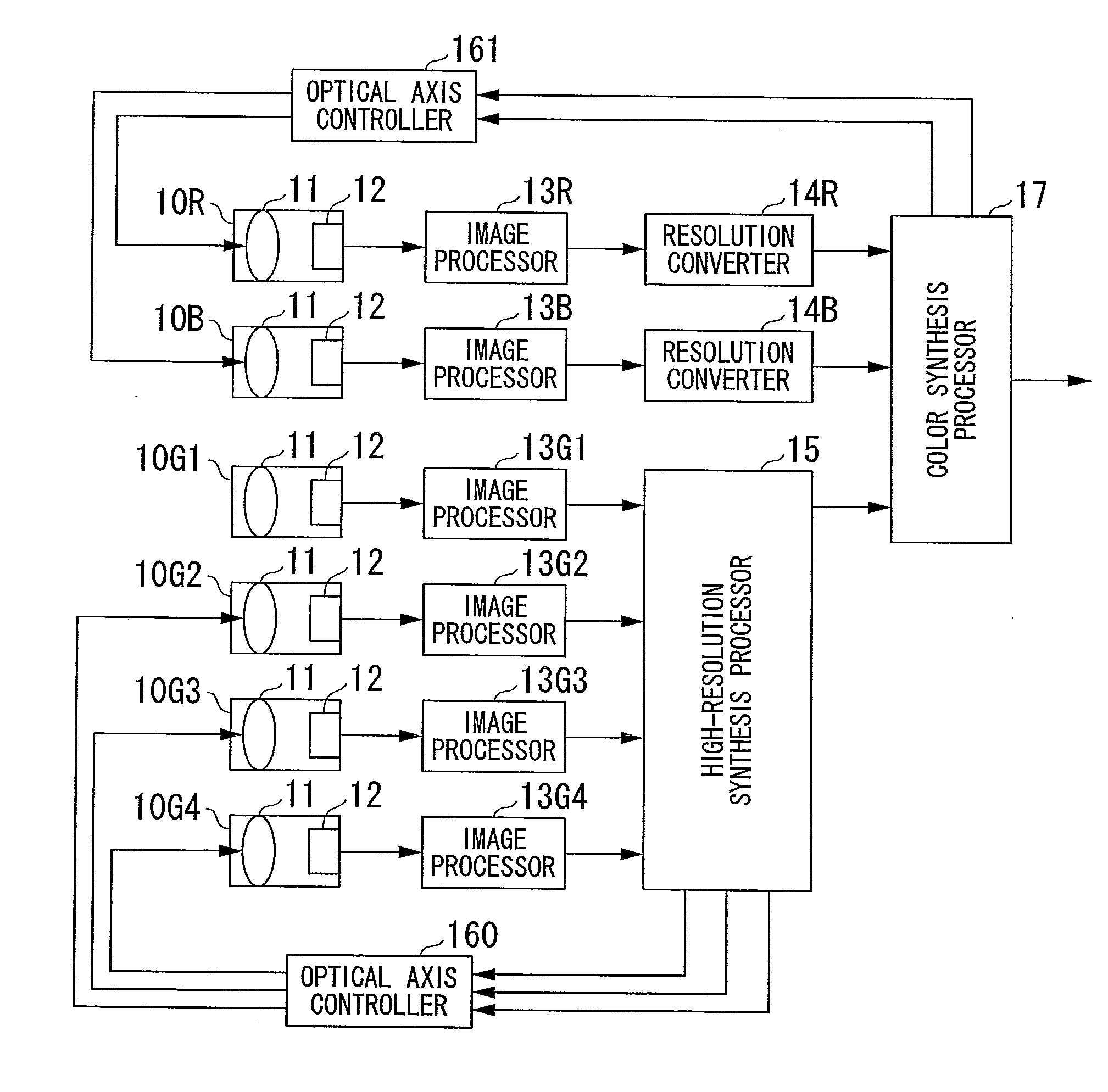
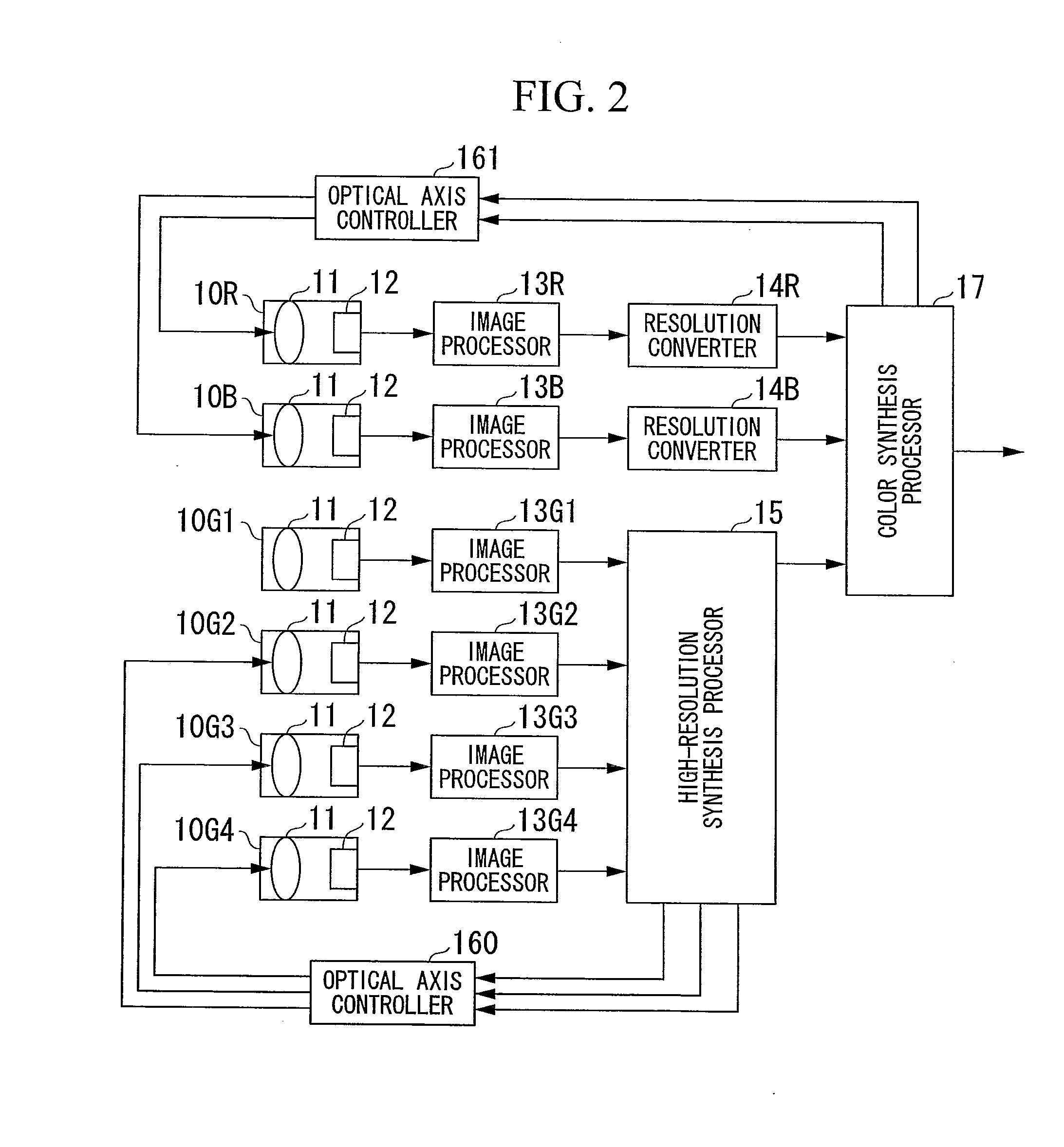
[0058]FIG. 2 is a block diagram showing a detailed configuration of the imaging device shown in FIG. 1. Each of the im...
second embodiment
[0091]Next, an imaging device according to a second embodiment of the present invention will be described with reference to the accompanying drawings. FIG. 17 shows an appearance of the imaging device in the second embodiment. Since the imaging device in the second embodiment includes three green image pickup units 10G1, 10G2, and 10G3, a red image pickup unit 10R, and a blue image pickup unit 10B provided in a row, as shown in FIG. 17, an elongated design can be obtained, unlike the first embodiment. A configuration of the imaging device in the second embodiment will be described with reference to FIG. 18.
[0092]The imaging device shown in FIG. 18 differs from the imaging device shown in FIG. 2 in that there are three green image pickup units and that correlation detection control is performed to correct a color shift in a previous stage of resolution converters 14R and 14B and a high-resolution synthesis processor 15. Since the green image pickup unit 10G1 is provided at the center...
third embodiment
[0102]Next, an imaging device according to a third embodiment of the present invention will be described with reference to the accompanying drawings. FIGS. 21A and 21B show an appearance of the imaging device in the third embodiment. As shown in FIGS. 21A and 21B, the imaging device in the third embodiment includes a red and blue image pickup unit 10B / R that is a combination of a red image pickup unit 10R and a blue image pickup unit 10B, unlike the first and second embodiments. In the red and blue image pickup unit 10B / R, red and blue color filters having the same size as a pixel are provided in a checker pattern on a surface of an image pickup element, such that both a red image and a blue image can be picked up. Use of the red and blue image pickup unit 10B / R reduces the size and realizes one-channel optical axis shift control in the color synthesis processor 17, thereby reducing a processing amount.
[0103]A configuration of the imaging device in the third embodiment will be descr...
PUM
 Abstract
Description
Claims
Application Information