Rapid changeover mechanism for bottom portions

a technology of changeover mechanism and bottom portion, which is applied in the direction of dough shaping, manufacturing tools, food shaping, etc., can solve the problems of dismantling in a relatively complex procedure, and achieve the effect of eliminating any operating errors

Active Publication Date: 2011-02-03
KRONES AG
View PDF7 Cites 10 Cited by
  • Summary
  • Abstract
  • Description
  • Claims
  • Application Information

AI Technical Summary

Benefits of technology

[0033]Locking and coupling the bottom mould (or the media connections thereof) are advantageously carried out automatically during withdrawal of the mould exchanger via two further curves. In this way it is possible to eliminate any operating errors by personnel, for example an incorrect locking or coupling.

Problems solved by technology

In the prior art, the bottom portions are usually screwed onto a carrier, and in the case of a tooling change will have to be dismantled in a relatively complex procedure.

Method used


Image

  • Rapid changeover mechanism for bottom portions
  • Rapid changeover mechanism for bottom portions
  • Rapid changeover mechanism for bottom portions

Examples


Embodiment Construction

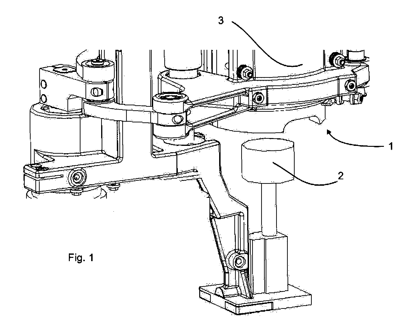
[0051]FIG. 1. shows a partial view of a blow moulding station 1 according to the disclosure. This blow moulding station 1 has here lateral portions 3 (only partially shown), which together with a bottom portion 2 (schematically shown) delimit a cavity (not shown). Reference numeral 1 identifies here the blow moulding station in its entirety. An apparatus according to the disclosure can here include a plurality of blow moulding stations, which may be arranged for example on a common carrier wheel.

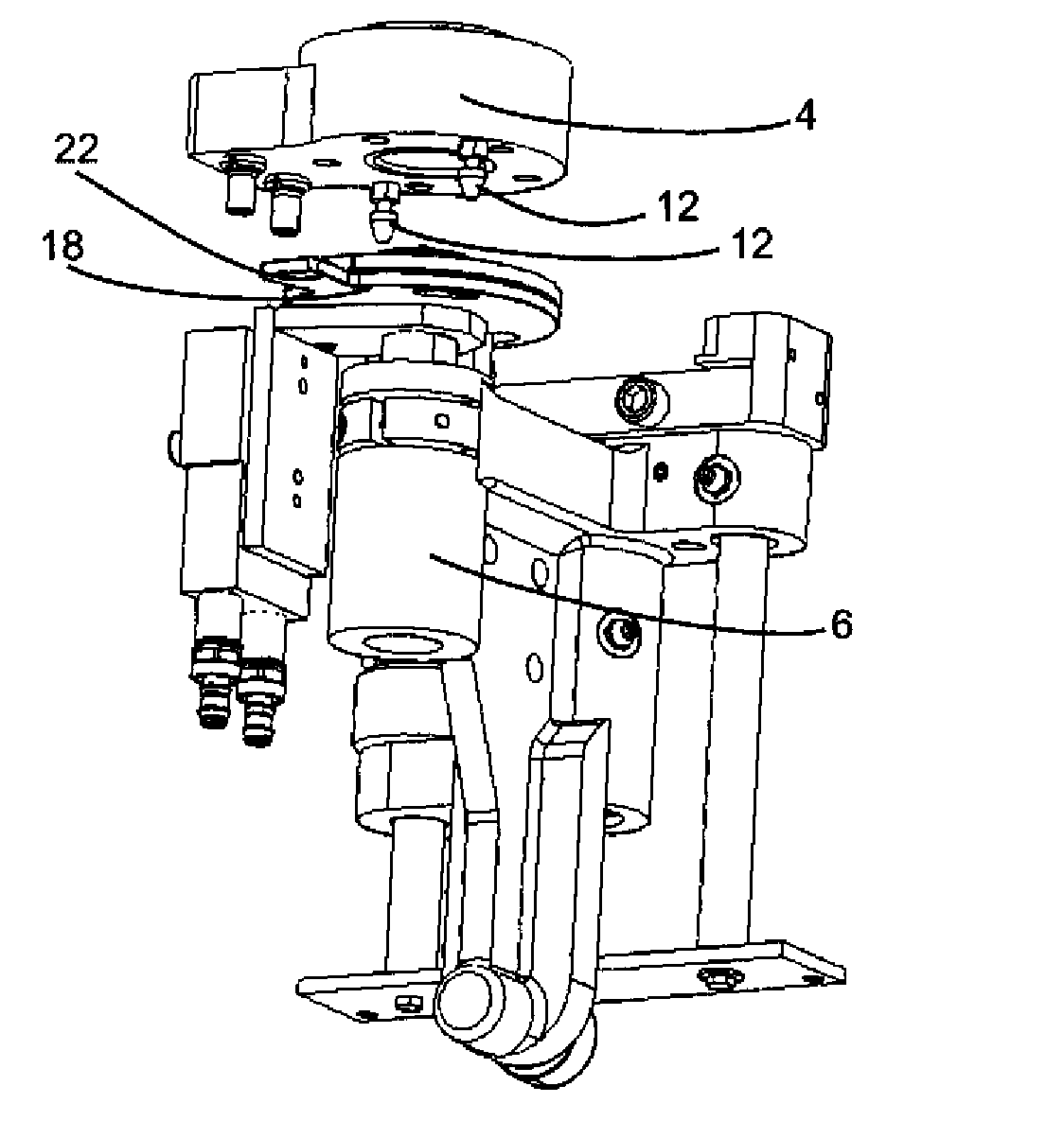
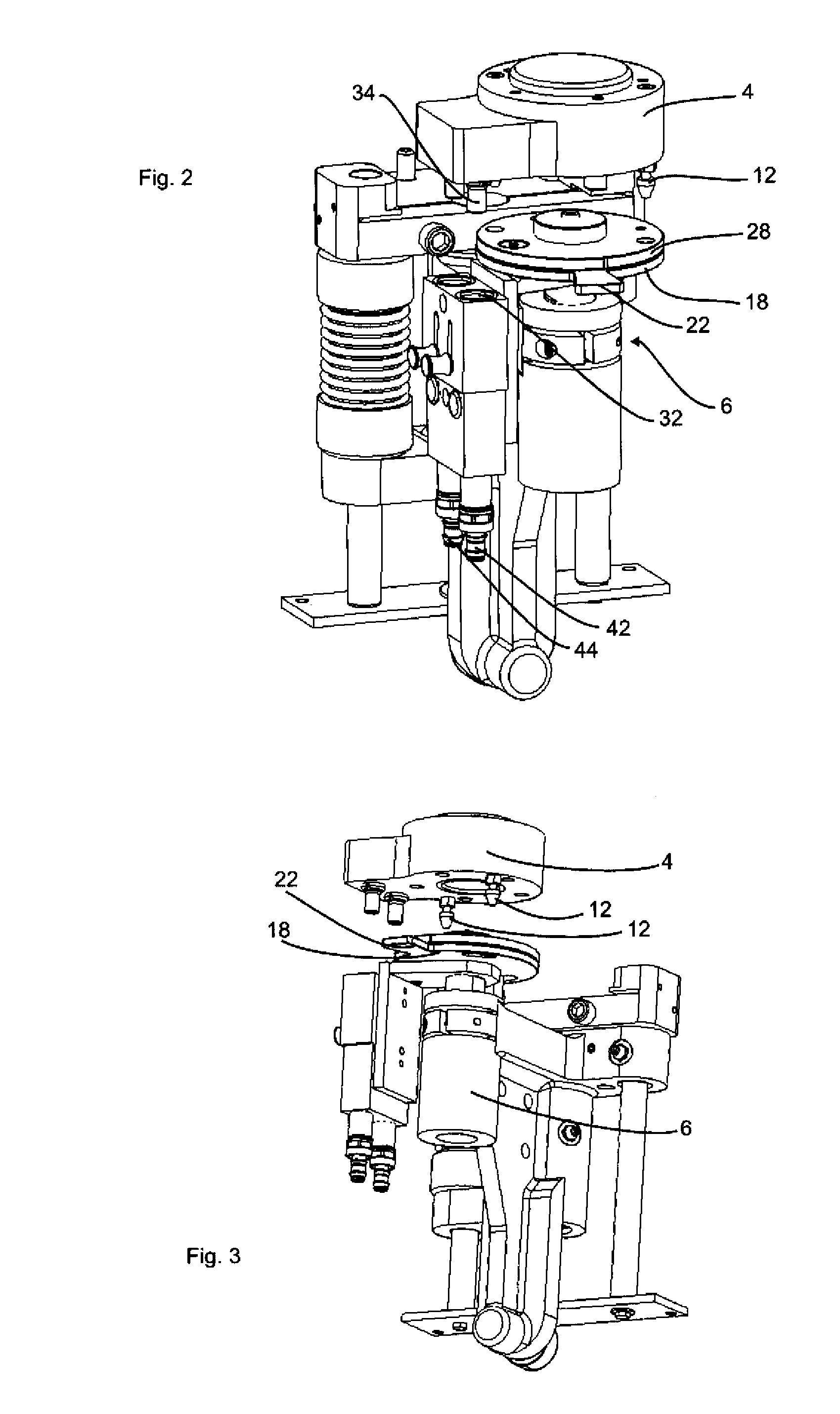
[0052]FIG. 2 shows a first view for illustrating the fastening mechanism. Here, an adapter element 4 is provided on which in turn the bottom portion (not shown) is fastened. Two pin-like bodies 12 are provided on this adapter element, but only one pin-like body 12 is visible. Further, a connection 34 is provided on the adapter element 4, which is used for supplying the coolant line within the adapter element 4 with liquid and in particular water. Adapter element 4 is here at the same time al...


PUM

PropertyMeasurementUnit
circumferenceaaaaaaaaaa
degree of stabilityaaaaaaaaaa
areaaaaaaaaaaa

Abstract

An apparatus for moulding plastic preforms into plastic containers may include at least one blow moulding station having a cavity. Within the cavity, the plastic preforms may be expanded into plastic containers. The blowing station has a bottom portion which delimits the cavity. The bottom portion is detachably disposed on a carrier by a fastening mechanism. The fastening mechanism has at least one pin-like body disposed on a first fastening element. The pin-like body engages in a condition in which the bottom portion is fastened to the carrier in a groove which is provided in a second fastening element. The pin-like body is displaceable relative to the carrier in the groove for fastening the bottom portion, and the groove is designed in such a way that an end section of the pin-like body may pass through the groove in a first section of the groove and cannot pass through the groove in a second section of the groove.

Description

CROSS-REFERENCE TO RELATED APPLICATION[0001]This application claims the benefit of priority of German Patent Application No. 10 2009 035 871.4, filed Jul. 31, 2009, pursuant to 35 U.S.C. 119(a)-(d), the disclosure of which is incorporated herein by reference in its entirety as if fully set forth herein.TECHNICAL FIELD[0002]The present disclosure relates generally to an apparatus for moulding plastic preforms into plastic containers and, more particularly, to a rapid changeover mechanism for bottom portions.BACKGROUND[0003]Apparatuses for moulding plastic preforms into plastic containers have been known from the prior art for a long time and usually include a plurality of blow-moulding stations arranged on a carrier wheel, and which are used for moulding plastic preforms into plastic containers by means of blow moulding.[0004]Here, blow moulding stations of this kind usually have two mould parts which, together with a bottom portion, delimit a cavity within which the plastic preforms...

Claims


Application Information

Patent Timeline
Patent Type & Authority Applications(United States)
IPC IPC(8): B29C49/42B29C49/64
CPCB29C33/30B29C33/306B29C49/42B29C2049/4889B29C2049/4856B29C2049/4858B29C49/48B29C2049/483B29C2049/4833B29C2049/4848B29C2049/4892B29C49/28008
Inventor STOIBER, CHRISTIANPHILIPP, THOMASEFFENBERGER, HARALD
Owner KRONES AG
Why Eureka
Try Eureka