
Central control and instrumentation system for a technical installation and method for operating a central control and instrumentation system

a technology of instrumentation system and central control, which is applied in the direction of instrumentation, total factory control, programme control, etc., can solve the problems of requiring a high overhead in the manufacture and maintenance of individual systems, and the comparatively high level of system complexity is produced, so as to achieve the effect of reducing time, cost and resources, and reducing the expenditure of producing software modules

Inactive Publication Date: 2011-02-03
SIEMENS AG
View PDF15 Cites 23 Cited by
  • Summary
  • Abstract
  • Description
  • Claims
  • Application Information

AI Technical Summary

Benefits of technology

[0010]The object underlying the invention is therefore to disclose a central control and instrumentation system for a technical installation of the aforementioned type by means of which the cited functionality range can be performed in a comparatively simple and resource-saving manner. A further object is to disclose a particularly suitable method for operating the central control and instrumentation system.
[0012]The invention is in this case based on the consideration that it is possible, by consistently refraining from providing different systems or engineering interfaces even in view of the multiplicity of desired functionalities, to cover a comparatively large number of functionalities such as, for example, realtime calculations on the one hand and diagnostic, verification, forecasting or other functionalities on the other hand with a system which is kept comparatively simple and hence with correspondingly low maintenance and installation overhead. In order nonetheless to be able to implement realtime-based automation workflows on the one hand and realtime-independent automation workflows on the other hand while having recourse to a standardized system and a standardized engineering interface, a runtime environment or platform should be provided which can be used both for cyclical realtime processing and for freely configurable calculation periods or workflows.
[0015]In another or alternative advantageous embodiment an event-driven parameter is provided as a triggering parameter. In this way it is made possible in particular for a process workflow to be controlled via a correspondingly parameterized and configured central control module substantially independently of the actual time sequence, but rather as a function of the event chains present in process logic terms. In this way it can be ensured, for example, that intermediate results required for the activation of one functional module are initially waited for and provided, with the following functional module being activated immediately after the arrival of said results or intermediate values as the triggering event. In an event-driven system of this kind individual process steps can be processed sequentially while the best possible use is made of the available system resources, in other words as quickly as possible.
[0017]The advantages achieved by means of the invention consist in particular in the fact that it is possible, by means of the selection possibility provided to the user, i.e. the triggering parameter, on the basis of which the functional modules are activated via the central control module, to specify as a function of situation or based on need the performance of a comparatively large number of process workflows and operating functionalities while maintaining a common runtime environment and within one and the same system. Through the thus enabled maintaining of a single runtime environment for different types of functionalities such as realtime calculations for automation on the one hand and also calculations for times in the past within the context of diagnostic or verification functions or in the future within the context of forecasting functions on the other hand it is possible to provide all the cited functionalities within one and the same system with a particularly low investment in terms of time, costs and resources.
[0018]It is therefore no longer necessary to have recourse to other modules or functional modules, in particular to external applications or separate systems such as simulators, for example. As a result the expenditure for producing software modules, engineering costs and the development costs for automation systems can also be kept particularly low overall, since the same functional building blocks or modules can always be used in all application areas.

Problems solved by technology

However, as a result of the individualization and implementation of systems that are so diverse per se for covering the necessary performance spectrum, a comparatively high level of system complexity is produced which in turn necessitates a high overhead in terms of the manufacture and maintenance of the individual systems.

Method used


Image

  • Central control and instrumentation system for a technical installation and method for operating a central control and instrumentation system
  • Central control and instrumentation system for a technical installation and method for operating a central control and instrumentation system

Examples


Embodiment Construction

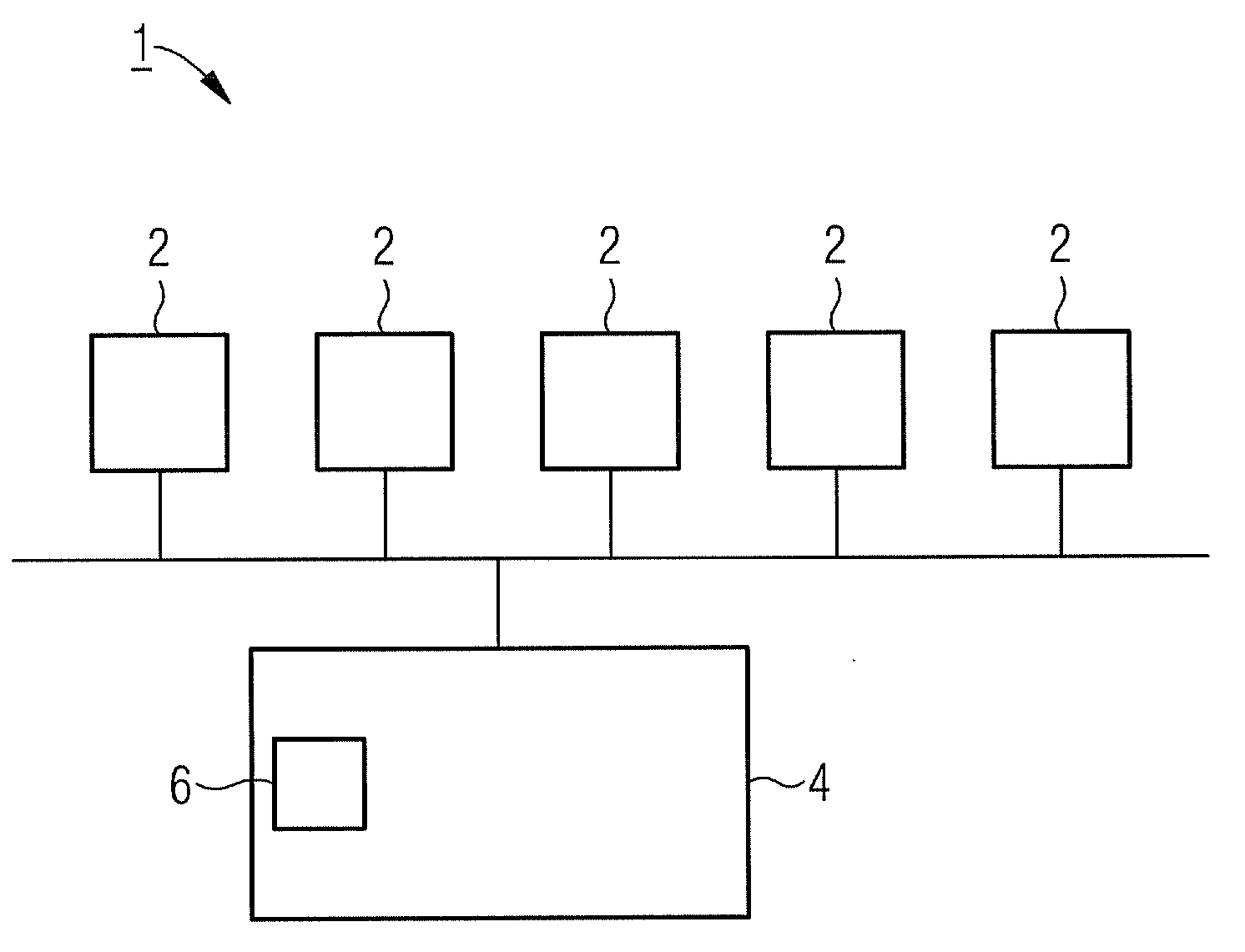
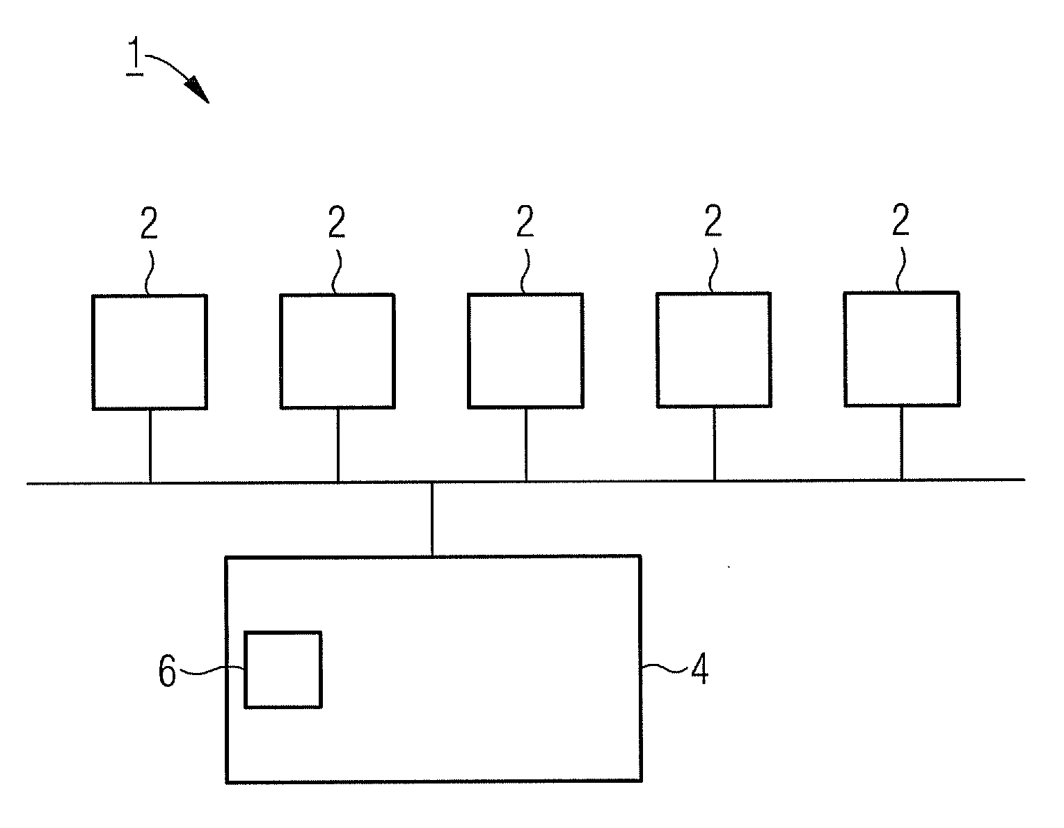
[0020]The central control and instrumentation system 1 according to the figure is provided for controlling and monitoring the system processes in a comparatively complex technical installation, namely in the exemplary embodiment of a power station. For that purpose the central control and instrumentation system 1 comprises a multiplicity of functional modules 2, each of which is specifically configured for performing individual functions or tasks within the framework of the overall process flow sequence. In this case the functional modules 2 can be embodied as separate hardware components, as independent software modules or as a combination of both. By means of the individual functional modules 2 the relevant components of the power station in particular can in this case be individually monitored in respect of their operating state and suitably controlled, wherein further functional modules 2 can be provided for the specific monitoring of measurement parameters, for determining inte...


PUM


Abstract

A central control and instrumentation system for a technical installation is provided. The central control and instrumentation system for a technical installation includes a plurality of functional modules which are interconnected for data transmission, monitored by a central control module and activated, when needed, as a function of a triggering parameter. The triggering parameter provided for activating the functional modules by the control module is predefined by a user.

Description

CROSS REFERENCE TO RELATED APPLICATIONS[0001]This application is the US National Stage of International Application No. PCT / EP2008 / 062159, filed Sep. 12, 2008 and claims the benefit thereof. The International Application claims the benefits of German application No. 10 2007 043 795.3 DE filed Sep. 13, 2007. All of the applications are incorporated by reference herein in their entirety.FIELD OF INVENTION[0002]The invention relates to a central control and instrumentation system for a technical installation, in particular a power station, comprising a plurality of functional modules which are interconnected for data communication purposes and which are monitored and where necessary activated by a central control module as a function of a triggering parameter. It further relates to a method for operating a central control and instrumentation system of said type.BACKGROUND OF INVENTION[0003]In large-scale technical installations such as, for example, power stations or the like, process ...

Claims


Application Information

Patent Timeline
IPC IPC(8): G05B15/02G05B19/048
CPCG05B19/0421G05B19/41865G05B2219/34417G05B2219/25367G05B2219/34258G05B2219/25343Y02P90/02
Inventor JORDAN, CARSTENSPEH, RAINERUNKELBACH, MICHAEL
Owner SIEMENS AG
Learn More