Evaporator and cooling circuit

a cooling circuit and evaporator technology, applied in the direction of indirect heat exchangers, domestic cooling devices, lighting and heating devices, etc., can solve the problems of low efficiency of evaporators, poor heat transfer performance of boiling, and difficulty in making leak proof at high pressur

Active Publication Date: 2011-02-10
ABB (SCHWEIZ) AG
View PDF17 Cites 23 Cited by
  • Summary
  • Abstract
  • Description
  • Claims
  • Application Information

AI Technical Summary

Benefits of technology

[0024]A benefit of the evaporation channel geometry described above can be that the heat transfer between the heat emitting device and the cooling liquid inside the evaporator as well as the fluid circulation can be improved by the evaporation channel geometry enabling bubble pumping.
[0025]Also, a benefit of the liquid return channels can be that they allow liquid cooling fluid, which may be present in the top collector or which may enter the top collector from the evaporation channels, to return to the bottom collector quickly and in an evenly distributed manner, such that the risk of the evaporator running dry can be reduced, even under strong thermal load. This includes the risk of the evaporator running dry locally.
[0037]Exemplary embodiments are also directed to methods of manufacturing the disclosed evaporator and cooling circuit.
[0038]Further advantages, features, aspects and details that can be combined with embodiments described herein are evident from the, the description and the drawings.

Problems solved by technology

A problem of such a cooling circuit can be that the evaporator at the same time provides the function of a liquid reservoir.
Consequently, the efficiency of the evaporator can be low because the introduced heat leads to boiling of the liquid which is provided in a large volume of the evaporator.
This so-called “pool boiling” has poor heat transfer performance, is bulky, requires a large fluid inventory, and can be difficult to make leak proof at high pressure.

Method used


Image

  • Evaporator and cooling circuit
  • Evaporator and cooling circuit
  • Evaporator and cooling circuit

Examples


first exemplary embodiment

of an Evaporator

Overall Design.

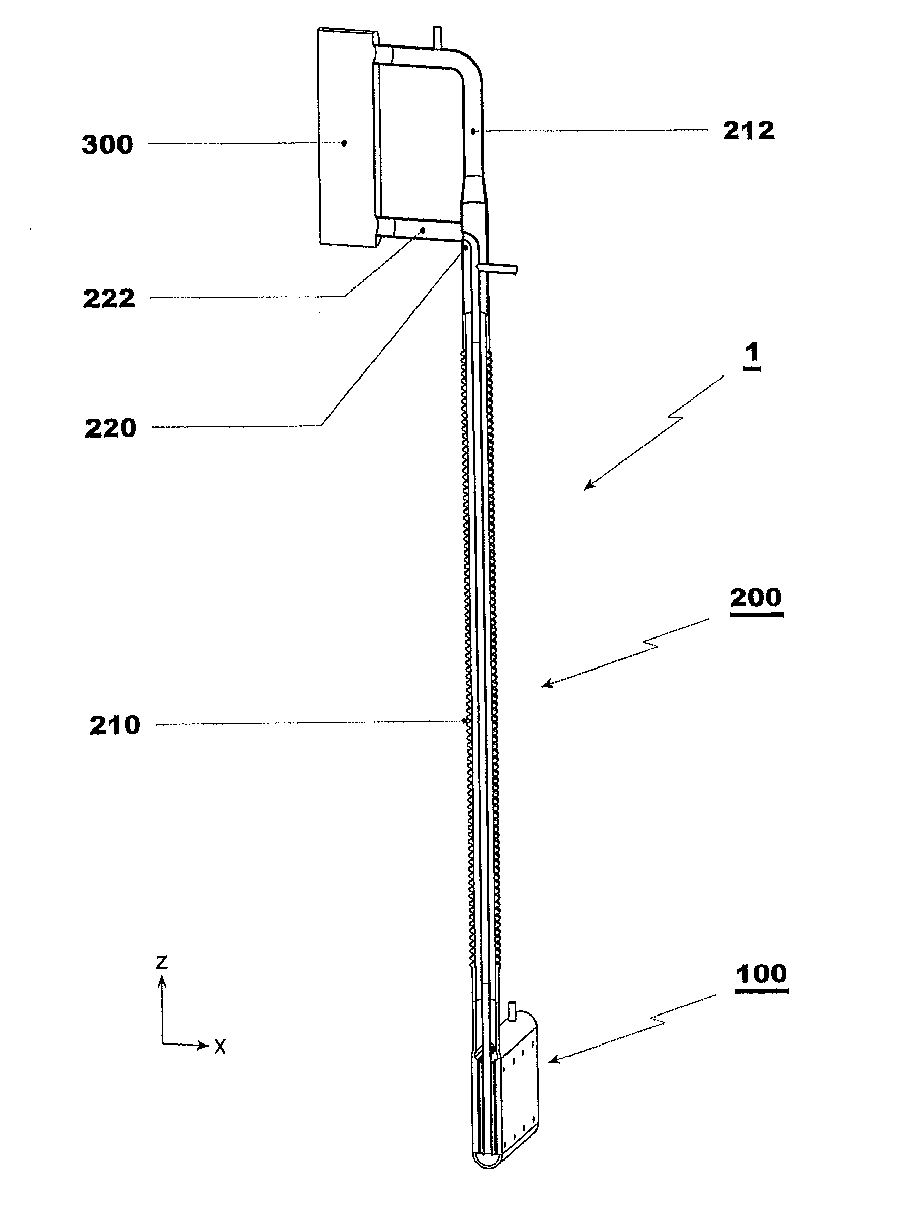
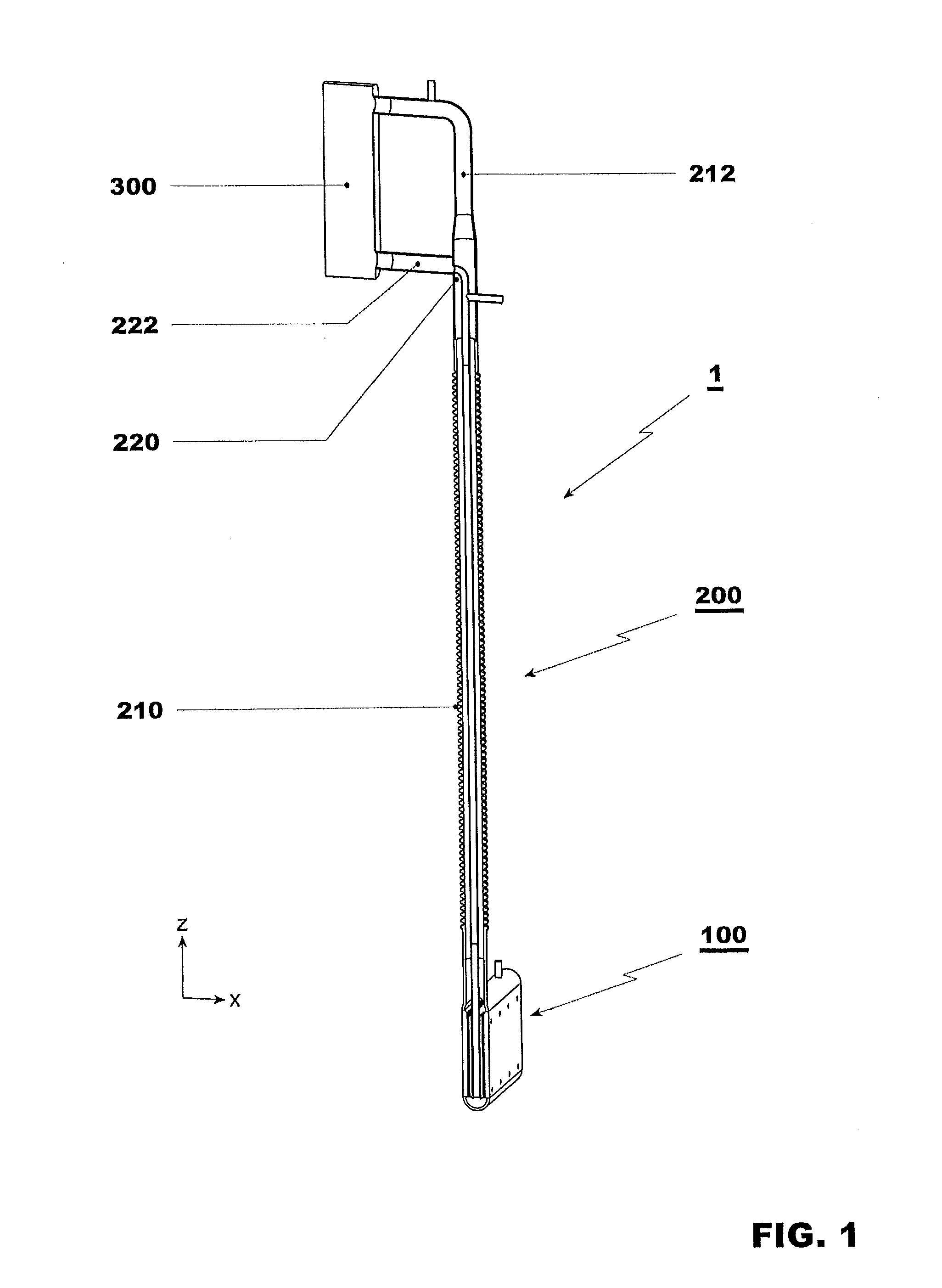
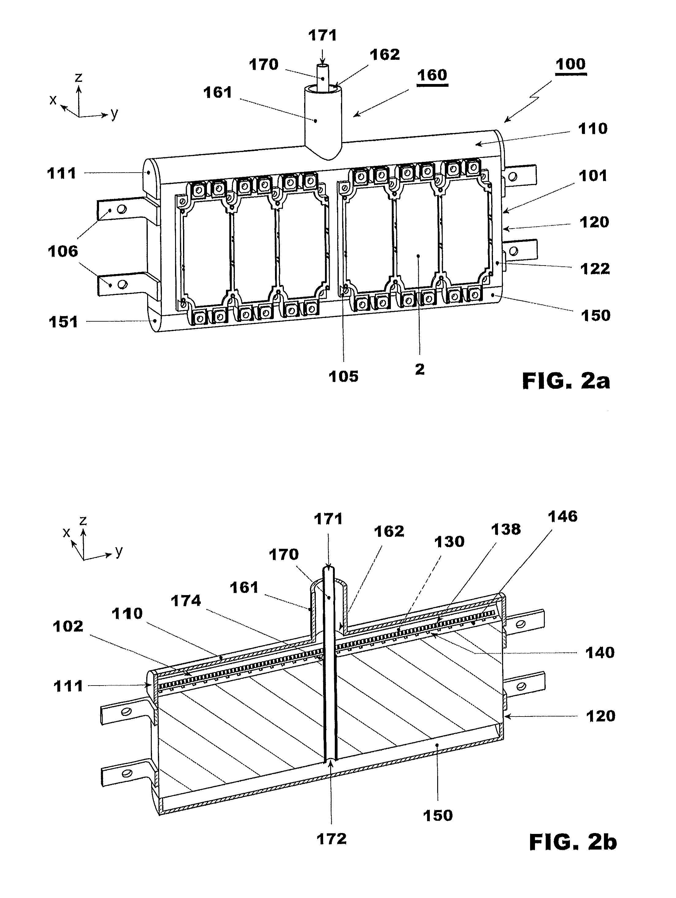
[0047]Referring to FIGS. 2a and 2b, the evaporator 100 is now described in more detail. Here, reference is made to the orthogonal x-y-z coordinate system shown in FIG. 2a and the other Figures, wherein the z axis denotes a direction of longitudinal extension of the evaporation channels 130 (see below), and wherein the x axis denotes the direction normal to the evaporator wall 122 (see below).

[0048]The evaporator 100 has an evaporator housing 101 including an inner volume for the cooling fluid. The interior volume can be accessible through a connector 160 forming a functional port for the vaporous and liquid condensate. Besides the connector 160, the interior volume of the evaporator 100 can be closed in a fluid-tight manner such as to contain the cooling fluid therein. The connector 160 includes an outer connector tube 161 that laterally encompasses an inner connector tube 170 in a coaxial manner with reference to an axis defined by the cylindrical sha...


PUM


Abstract

An evaporator for a cooling circuit is provided, for cooling at least one heat emitting device by evaporation of a cooling fluid. The evaporator includes a top collector, a bottom collector, and an evaporator body. The evaporator body includes at least one thermoconducting wall that is thermally connectable to the at least one heat emitting device, a plurality of evaporation channels, and a plurality of return channels.

Description

RELATED APPLICATION[0001]This application claims priority under 35 U.S.C. §119 to European Patent Application No. 09167267.5 filed in Europe on Aug. 5, 2009, the entire content of which is hereby incorporated by reference in its entirety.FIELD[0002]The disclosure relates to an evaporator for a cooling circuit, for example, a cooling circuit for cooling a heat emitting device by evaporation of a cooling fluid, to a cooling circuit and to a power module including such an evaporator, and to a method of cooling a heat emitting device by an evaporator.BACKGROUND INFORMATION[0003]As power electronic devices utilize more power and consequently dissipate more heat, efficient cooling of such power electronic devices is important. One way of providing an efficient cooling system for such power electronic devices, for example, semi-conductor switching elements, is providing a two-phase cooling circuit. Such a cooling circuit brings a liquid into thermal contact with a device emitting heat. The...

Claims


Application Information

Patent Timeline
Patent Type & Authority Applications(United States)
IPC IPC(8): F25D17/02F25B39/02F25B41/00F25D31/00
CPCF28D15/0266H05K7/20936H01L2924/0002H01L2924/00
Inventor AGOSTINI, FRANCESCOYESIN, BERKAGOSTINI, BRUNO
Owner ABB (SCHWEIZ) AG
Why Eureka
Try Eureka