Static pressure Anti-stow logic for platform wheelchair lifts

a platform and anti-stow logic technology, applied in the field of platform wheelchair lifts, can solve the problems of increasing the difficulty of detecting the weight on the platform, the platform cannot be able to stow a weight greater than 50 pounds, and the platform cannot be positioned anywhere on the platform, so as to reduce the pressure of the hydraulic circuit

Active Publication Date: 2011-02-10
RICON
View PDF18 Cites 4 Cited by
  • Summary
  • Abstract
  • Description
  • Claims
  • Application Information

AI Technical Summary

Benefits of technology

The method may further include the step of positioning the platform at an entry position that is level with a floor of a vehicle, The method may also include the steps of sending a signal to a pump to raise the pressure of the hydraulic circuit prior to measuring the static pressure of the hydraulic circuit, and sending a signal to a valve to reduce the pressure of the hydraulic circuit to a weight detection level. The valve may be a poppet valve. Further, the method may include the steps of moving a switch to an open position when the measured static pressure has a higher value than the baseline pressure, and preventing the platform lift from moving into a stowed position within a vehicle when the switch is in the open position. The switch may be a pressure switch. The method may also include the step of moving the platform wheelchair lift into a stowed position within a vehicle when the switch is in a closed position.

Problems solved by technology

Previous federal regulations provided that the platform cannot be capable of stowing a weight greater than 50 pounds.
However, a new regulation was promulgated which provides that the platform cannot be capable of stowing a weight greater than 50 pounds positioned anywhere on the platform.
As the 50 pound weight is moved closer to the platform pivot, detecting the weight on the platform becomes more difficult by measuring an increase in the dynamic pressure during a stow attempt.
If the 50 pound weight is placed at the platform pivot or behind the platform pivot, detecting the 50 pounds by measuring an increase in dynamic pressure is substantially ineffective.
Detecting weight on the platform becomes more difficult as the pressure required to fold the platform is closer a hydraulic circuit pressure level that exists when there is no weight positioned on the platform during a stow attempt.
In other words, if the weight is positioned closer to the pivot point, the difference in the dynamic pressure of the hydraulic circuit with weight and without weight on the platform becomes smaller, which can result in false readings that weight is present on the platform.

Method used


Image

  • Static pressure Anti-stow logic for platform wheelchair lifts
  • Static pressure Anti-stow logic for platform wheelchair lifts
  • Static pressure Anti-stow logic for platform wheelchair lifts

Examples


Embodiment Construction

For purposes of the description hereinafter, spatial orientation terms, if used, shall relate to the referenced embodiment as it is oriented in the accompanying drawing figures or otherwise described in the following detailed description. However, it is to be understood that the embodiments described hereinafter may assume many alternative variations and embodiments. It is also to be understood that the specific embodiments illustrated in the accompanying drawing figures and described herein are simply exemplary and should not be considered as limiting.

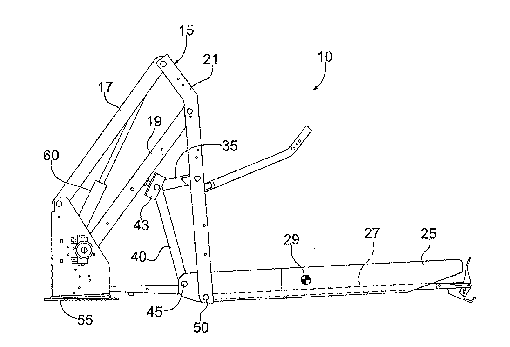
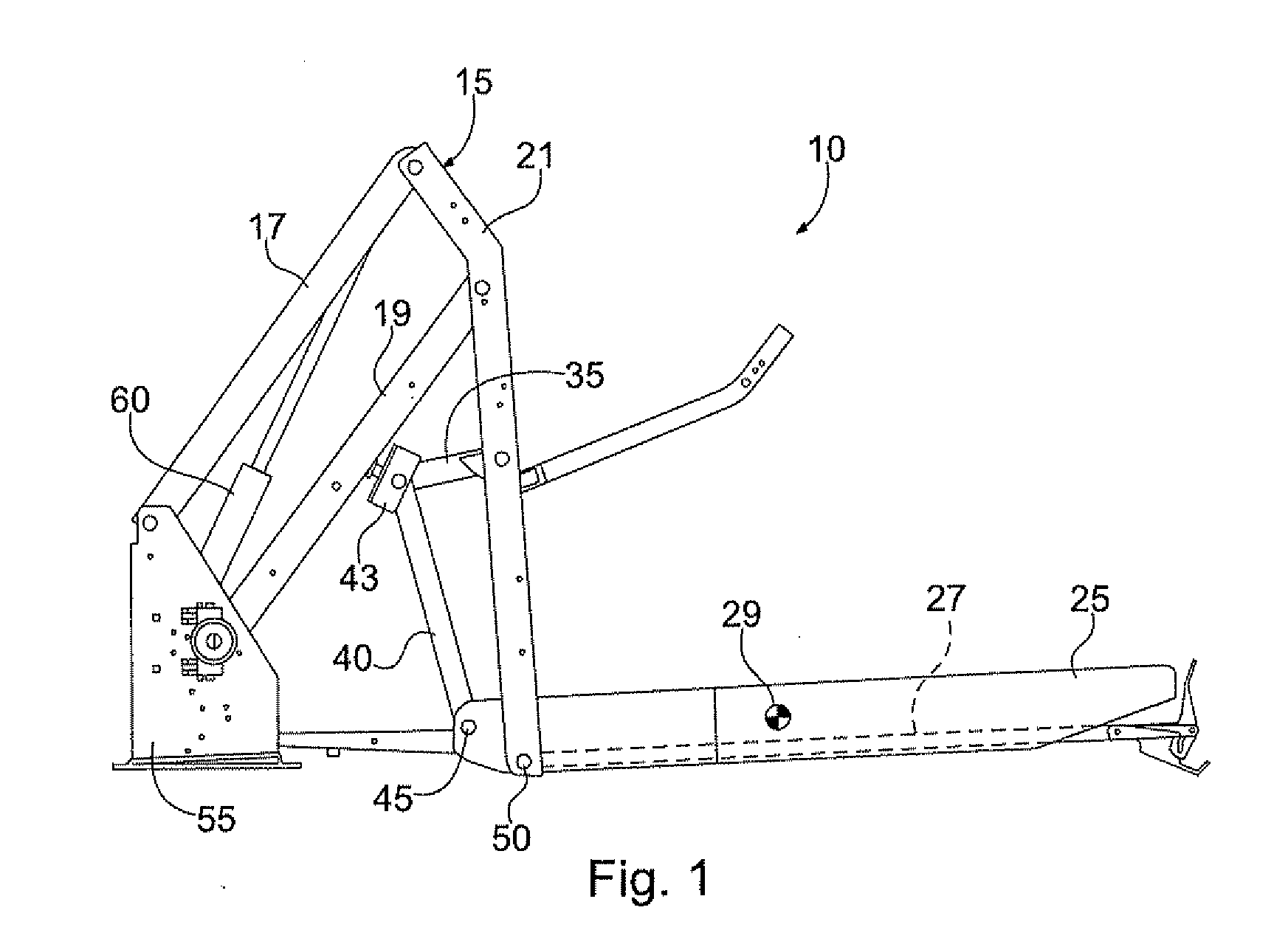
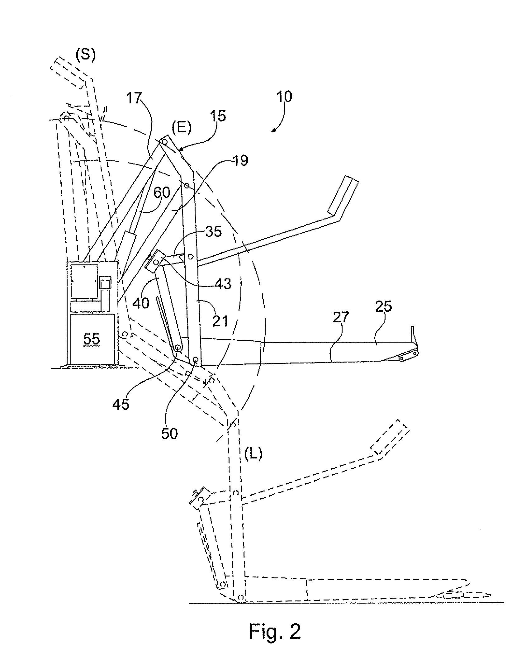
In one embodiment, shown in FIGS. 1-3, a platform wheelchair lift 10 is provided having a parallelogram mechanism 15, a platform 25, a base plate 55, a pair of hydraulic cylinders 60, and a hydraulic circuit 75. The parallelogram mechanism 15 includes a pair of spaced apart upper arms 17 and a pair of spaced apart lower arms 19 pivotally secured at an outboard end (remote from the base plate 55) to corresponding vertical links 21 and ...


PUM


Abstract

A method for detecting weight on a platform lift having a platform, a hydraulic cylinder, and a hydraulic circuit including the steps of measuring a static pressure of the hydraulic circuit, and comparing the measured static pressure to a baseline pressure of the hydraulic circuit. The baseline pressure is a static pressure of the hydraulic circuit without external weight positioned on the platform.

Description

BACKGROUND OF THE INVENTION1. Field of the InventionThis invention relates generally to platform wheelchair lifts and, more particularly, to a method for detecting weight on a platform wheelchair lift prior to stowage.2. Description of Related ArtWheelchair lifts typically include mobile platforms to raise and lower passengers between a loading position at a ground level and an entry position at the vehicle's floor level. Further, the wheelchair lifts are usually collapsible for storage, i.e., stowed, within the vehicle. Thus, the wheelchair lifts may include a load platform that is driven through motion patterns to attain loading, entry, and storage positions. In one type of wheelchair lift, the lift is provided with a parallelogram structure to carry a platform that receives the wheelchair. The lift also includes a hydraulic system for actuating the platform through the parallelogram mechanism and a control unit for controlling the different motion patterns to raise and lower the ...

Claims


Application Information

Patent Timeline
Patent Type & Authority Applications(United States)
IPC IPC(8): G01G19/10
CPCA61G3/062B66B9/0853
Inventor DELEO, DANTE V.FISHER, STEVEN
Owner RICON
Why Eureka
Try Eureka