Clutch Brake
- Summary
- Abstract
- Description
- Claims
- Application Information
AI Technical Summary
Benefits of technology
Problems solved by technology
Method used
Image

Examples
Embodiment Construction
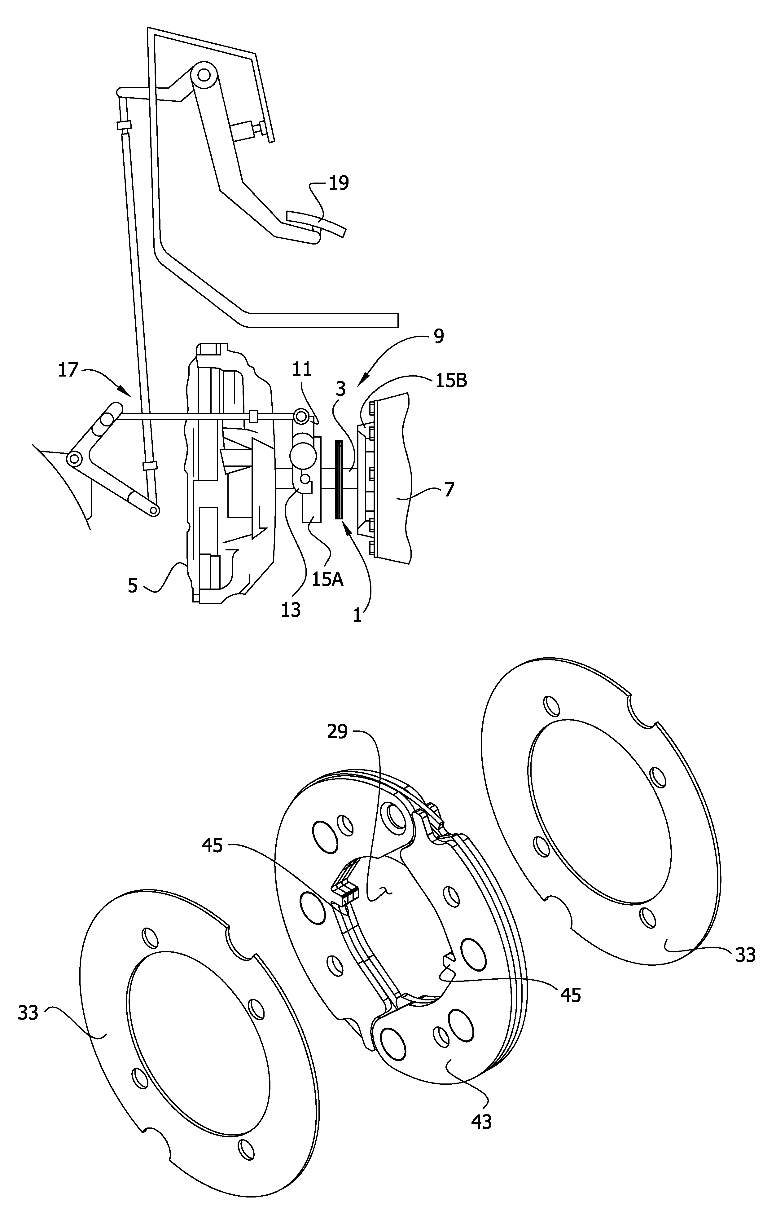
[0015]Referring to FIG. 1 of the drawings, a clutch brake, generally indicated at 1, is shown as part of a clutch brake assembly used for braking rotation of a shaft 3 connecting an engine 5 to a transmission 7. The clutch brake 1 is mounted for rotation in unison with the shaft 3 and for sliding movement along the shaft. The clutch brake 1 cooperates with a braking mechanism 9 to slow rotation of the shaft 3 when the transmission is changing gears.
[0016]The braking mechanism 9 comprises a yoke 11, fingers 13 on the yoke, and a pair of clutch plates 15A, 15B mounted on the shaft. In general, each clutch plate 15A, 15B is a bearing housing cover having a friction surface at one side of the cover. The clutch brake 1 is located between the two clutch plates 15A, 15B. The yoke 11 is connected by a linkage 17 to a foot pedal 19 which is used to pivot the yoke between a free-rotation position in which the clutch brake 1 and the two clutch plates 15A, 15B are spaced from one another and th...
PUM
 Abstract
Description
Claims
Application Information
 - R&D Engineer
- R&D Manager
- IP Professional
- Industry Leading Data Capabilities
- Powerful AI technology
- Patent DNA Extraction
Browse by: Latest US Patents, China's latest patents, Technical Efficacy Thesaurus, Application Domain, Technology Topic.
© 2024 PatSnap. All rights reserved.Legal|Privacy policy|Modern Slavery Act Transparency Statement|Sitemap