Wireless IC device

a technology of integrated circuits and wires, applied in the direction of printed circuit aspects, antenna earthings, instruments, etc., to achieve the effect of effective control of the gain of transmission and reception signals

Active Publication Date: 2011-02-10
MURATA MFG CO LTD
View PDF100 Cites 115 Cited by
  • Summary
  • Abstract
  • Description
  • Claims
  • Application Information

AI Technical Summary

Benefits of technology

[0010]In the wireless IC device according to a preferred embodiment of the present invention, the radiation plate preferably includes the opening provided in a portion thereof and the slit connected to the opening and, when viewed in plan from the direction of the winding axis of the coil pattern in the power-supply circuit board, the opening in the radiation plate overlaps with at least a portion of an inner area of the coil pattern. Accordingly, when a current flows through the coil pattern, a magnetic field that is excited is ideally dist

Problems solved by technology

However, a satisfactory configuration for successfully

Method used


Image

  • Wireless IC device
  • Wireless IC device
  • Wireless IC device

Examples


first preferred embodiment

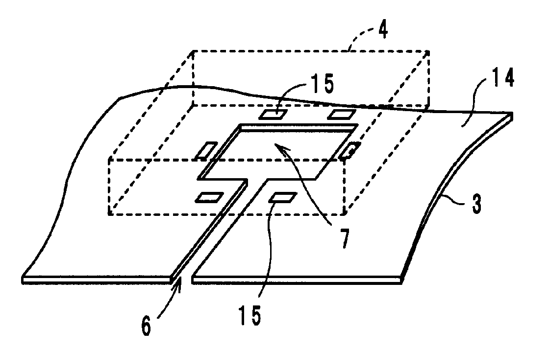
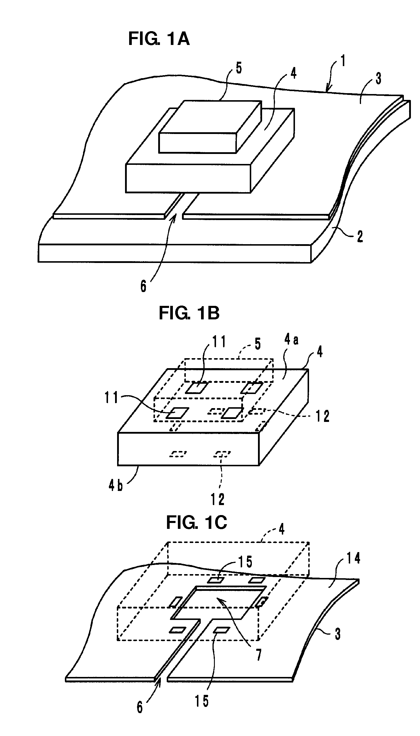
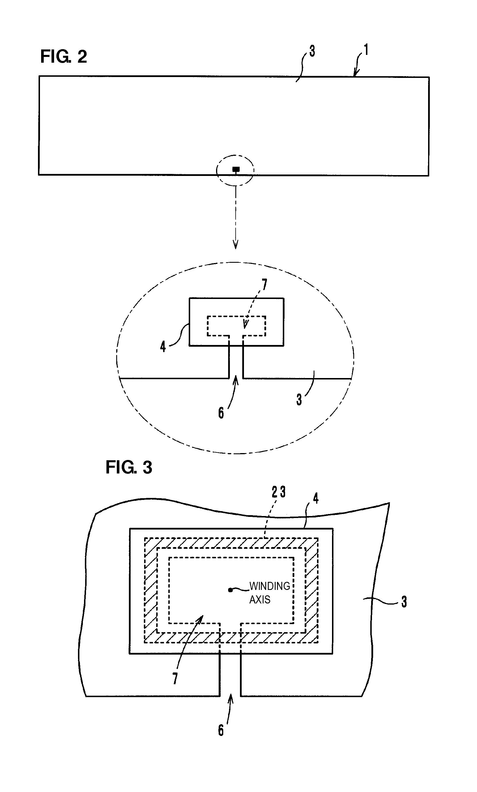
[0032]The configuration of a wireless IC device of a first preferred embodiment of the present invention will now be described with reference to FIGS. 1A to 1C. As shown in FIGS. 1A to 1C, in a wireless IC device 1, a radiation plate 3 defined by a metallic film, such as a metallic foil, for example, is provided on a support base 2, which is, for example, a printed circuit board. A power-supply circuit board 4 is mounted on the radiation plate 3. The power-supply circuit board 4 includes a power supply circuit including at least one coil pattern, and a wireless IC chip 5 arranged to process a specific radio signal is mounted on the power-supply circuit board 4. Specifically, the wireless IC chip 5 is mounted on one main surface 4a of the power-supply circuit board 4, and the power-supply circuit board is mounted on the radiation plate 3 with the other main surface 4b of the power-supply circuit board 4 defining the mounting surface. The wireless IC chip 5 includes a clock circuit, a...

second preferred embodiment

[0056]As shown in FIG. 8A, a wireless IC device 31 of a second preferred embodiment of the present invention is similar to the wireless IC device 1 of the first preferred embodiment. The wireless IC device 31 of the second preferred embodiment differs from the wireless IC device 1 of the first preferred embodiment in that a power-supply circuit board 34 is arranged along a side edge of a radiation plate 33. In the wireless IC device 31, the length, refer to as L1 in FIG. 5B, of a slit 36 extending from the side edge of the radiation plate 33 to an opening 37 is decreased and, thus, the gain tends to be decreased. In addition, as shown in FIG. 8B, the width of a slit 36′ provided in a radiation plate 33′ may be approximately the same as the width of an opening 37′.

[0057]Specific numerical values of the gain depending on the numerical value of the length L1 of the slit 36 will now be described when the radiation plate 33 has a length of about 14 cm and a width of about 4 cm.[0058]When...

third preferred embodiment

[0066]A wireless IC device 61 of a third preferred embodiment of the present invention differs from the wireless IC device 1 of the first preferred embodiment in that a radiation plate 63 is provided inside a support base 62, as shown in FIG. 10. In other words, ground electrodes provided inside the support base 62, for example, a printed circuit board, are used as the radiation plate 63.

[0067]Specifically, as shown in FIG. 10, in the wireless IC device 61, the radiation plate 63 including an opening 67 to which a slit (not shown) is connected is provided inside the support base 62. In addition, the power-supply circuit board 4 is mounted on the support base 62. The power-supply circuit board 4 includes a power supply circuit including the coil pattern 23. Furthermore, the wireless IC chip 5 arranged to process a specific radio signal is mounted on the surface of the power-supply circuit board 4.

[0068]Mounting electrodes 68 arranged to mount the power-supply circuit board 4 are prov...


PUM


Abstract

A wireless IC device includes a wireless IC chip arranged to process a radio signal, a power-supply circuit board that is connected to the wireless IC chip and that includes a power supply circuit including at least one coil pattern, and a radiation plate arranged to radiate a transmission signal supplied from the power-supply circuit board and/or receiving a reception signal to supply the reception signal to the power-supply circuit board. The radiation plate includes an opening provided in a portion thereof and a slit connected to the opening. When viewed in plan from the direction of the winding axis of the coil pattern, the opening in the radiation plate overlaps with an inner area of the coil pattern and the area of the inner area is approximately the same as that of opening.

Description

BACKGROUND OF THE INVENTION[0001]1. Field of the Invention[0002]The present invention relates to wireless integrated circuit (IC) devices including wireless ICs and radiation plates. More particularly, the present invention relates to a wireless IC device used in a radio frequency identification (RFID) system.[0003]2. Description of the Related Art[0004]RFID systems have been developed as article management systems in recent years. In such a RFID system, a reader-writer that generates an induced magnetic field communicates with an IC tag (hereinafter referred to as a wireless IC device) that is attached to an article and that stores information by a non-contact method using the electromagnetic field to transfer information.[0005]The wireless IC device used in an RFID system includes a wireless IC chip arranged to process a specific radio signal and a radiation plate arranged to transmit and receive the radio signal. For example, a known wireless IC device is described in WO 2007 / 083...

Claims


Application Information

Patent Timeline
IPC IPC(8): G06K19/077
CPCG06K19/07749G06K19/07779G06K19/07781G06K19/07783G06K19/0775H01Q7/00H05K1/0243G06K19/0723G06K19/07784H01L2224/16225G06K19/0709H05K2201/10098H01Q1/2225H01Q1/48
Inventor KATO, NOBORUIKEMOTO, NOBUO
Owner MURATA MFG CO LTD
Why Eureka
Try Eureka