

Lamp having self-regulated lighting
a technology of self-regulation and lamp, which is applied in the direction of electrical equipment, electric variable regulation, instruments, etc., can solve the problems of sensor not regulating the light source it senses, insufficient illumination of beams onto far-away objects, and certain visual discomfort, so as to achieve the effect of increasing the lighting performan
- Summary
- Abstract
- Description
- Claims
- Application Information
AI Technical Summary
Benefits of technology
Problems solved by technology
Method used
Image

Examples
first embodiment
[0043] illustrated in FIG. 4, the power of lighting module 11 is determined by a pair of resistors R1, R2 connected with the LED to the terminals of power source 12. First resistor R1 is connected in series with the LED, and second resistor R2 is connected in parallel to the terminals of first resistor R1 by a switch 18 which is controlled by the output of a comparator circuit 19 of Schmitt trigger type with operational amplifier. Control signal S from optic sensor 14 is applied to input E2 of comparator circuit 19. The other input E1 receives a setpoint value corresponding to the threshold of comparator circuit 19.
[0044]Depending on whether the value of signal S from sensor 14 is above or below the threshold of comparator circuit 19, switch 18 is open or closed so as to modify the value of the resistance in series with diode LED. This results in a variation of the lighting power of the LED, in particular a maximum power and a reduced power.
[0045]FIG. 5 is an alternative embodiment ...
second embodiment
[0048]FIG. 6 represents a block diagram of a servo-control circuit 20. The power of the LED is adjusted by a power converter 21 having a modulation input controlled by a first manual setpoint C1 displayed by the user in a first error circuit 22, and an automatic setpoint linked to the response of optic sensor 14. Setpoint C1 can correspond to a certain power level desired by the user. Signal S delivered by sensor 14 is compared in a second error circuit 23 with a second setpoint C2 corresponding to a desired lighting level. The output signal of second error circuit 23 is amplified in an amplifier 24 and applied to a third error circuit 25 which receives a measurement signal S1 of the current intensity flowing in a resistor R3 in series with the LED. The output of third error circuit 25 is connected to first error circuit 22 by means of an amplifier 26. The power of the LED is thus servo-controlled to first manual setpoint C1 and to the automatic setpoint coming from optic sensor 14 ...
third embodiment
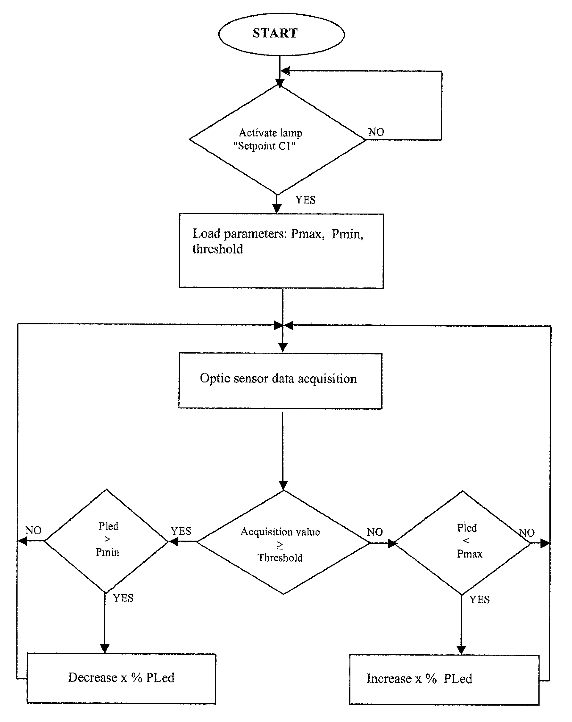
[0049] represented in FIG. 7, digital control circuit P comprises a microcontroller 27 which controls the power of the LED according to manual setpoint C1 and to the acquisition of optic sensor 14. The flowchart is illustrated in FIG. 8 and comprises the following steps:[0050]activation of lamp 10 and input of first setpoint C1 by the user to define the power level or another desired function;[0051]loading of power parameters Pmax, Pmin and of second lighting setpoint C2;[0052]acquisition of data from optic sensor 14;[0053]comparison of the data with the threshold fixed by second setpoint C2 to regulate the power of the LED.
[0054]In a too bright lighting state, the acquisition value from optic sensor 14 is higher than second setpoint C2. If at the same time the power of the LED is greater than Pmin, microcontroller 27 will command a decrease of x% of the power of the LED.
[0055]In an insufficient lighting state, the acquisition value from optic sensor 14 is lower than second setpoint...
PUM
 Abstract
Description
Claims
Application Information