Lighting device, display device and television receiver

a technology of display device and light source, which is applied in the direction of point-like light source, lighting and heating apparatus, instruments, etc., can solve the problems of increasing the cost of backlight device, increasing the number of lamps, and deteriorating the display quality of liquid crystal display device, so as to achieve cost reduction and power saving

Inactive Publication Date: 2011-02-10
SHARP KK
View PDF13 Cites 8 Cited by
  • Summary
  • Abstract
  • Description
  • Claims
  • Application Information

AI Technical Summary

Benefits of technology

[0008]The present invention was made in view of the foregoing circumstances. An object of the present invention is to provide a lighting device in which light emitted from a light source is effectively used to ensure unifo

Problems solved by technology

However, if the linear light is not sufficiently converted into the planer light, striped lamp images are generated along the alignment of the fluorescent tubes, and this deteriorates display quality of the liquid crystal display device.
However, increase o

Method used


Image

  • Lighting device, display device and television receiver
  • Lighting device, display device and television receiver
  • Lighting device, display device and television receiver

Examples


first embodiment

[0050]The first embodiment of the present invention will be explained with reference to FIGS. 1 to 8.

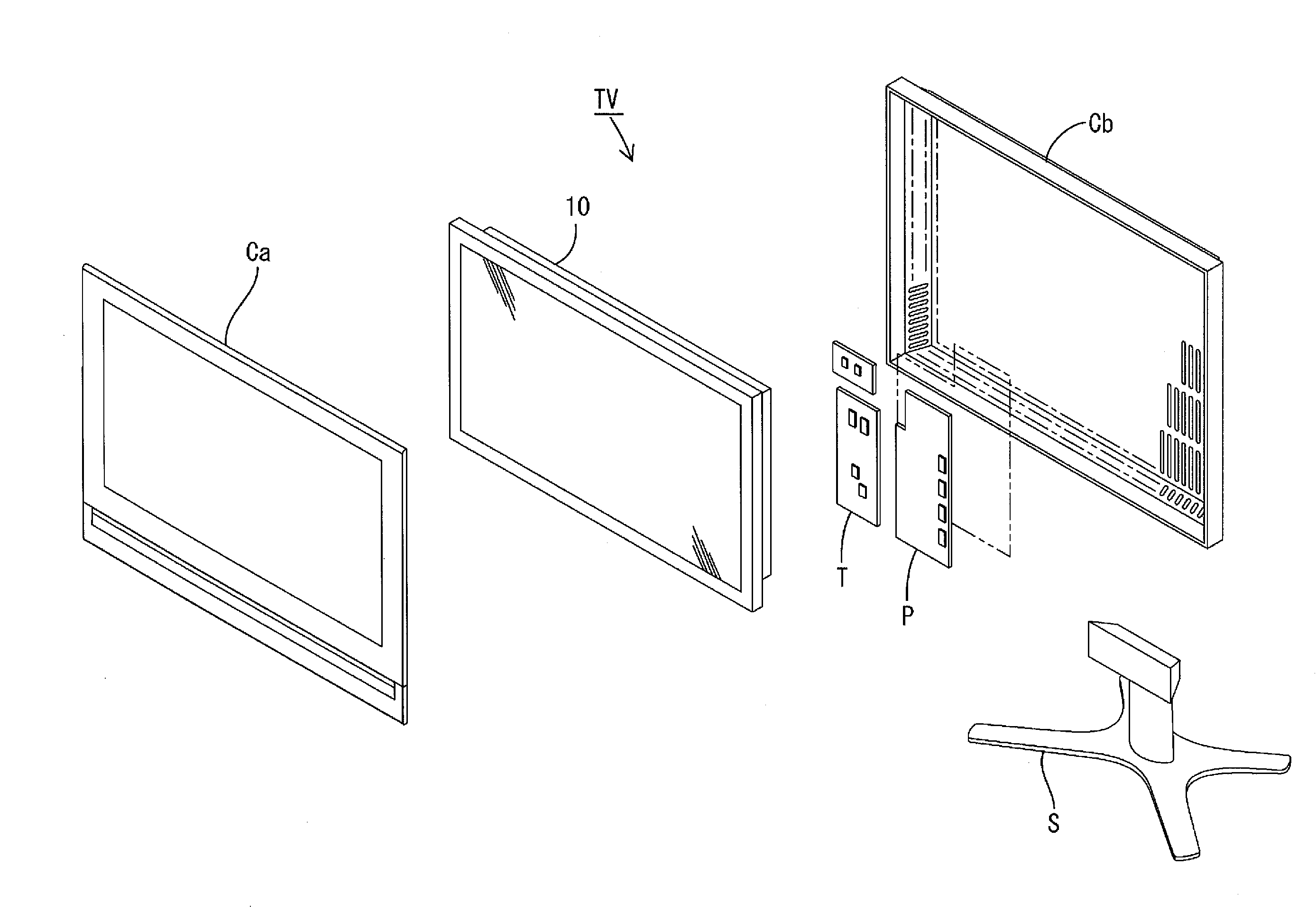
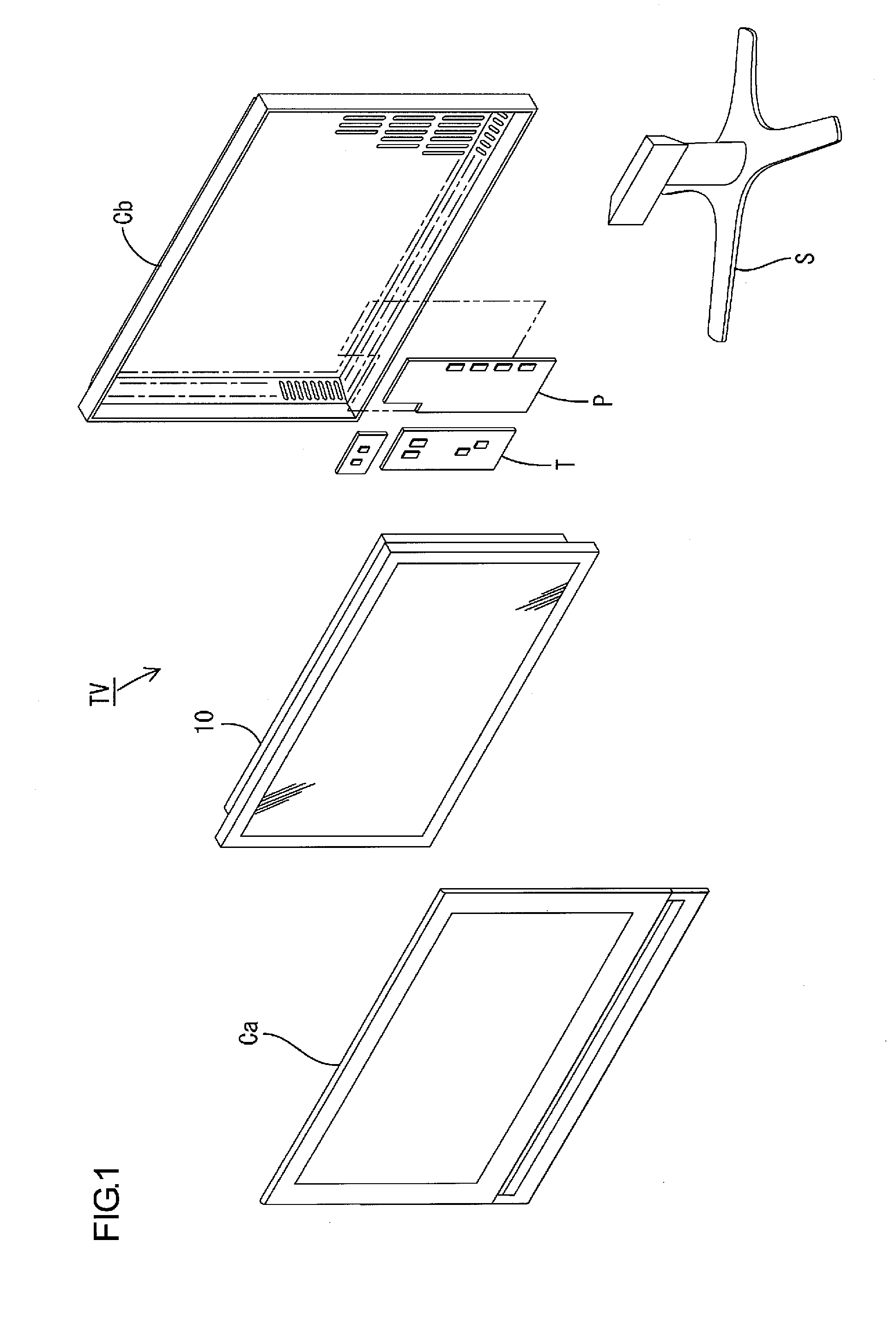
[0051]First, a construction of a television receiver TV including a liquid crystal display device 10 will be explained.

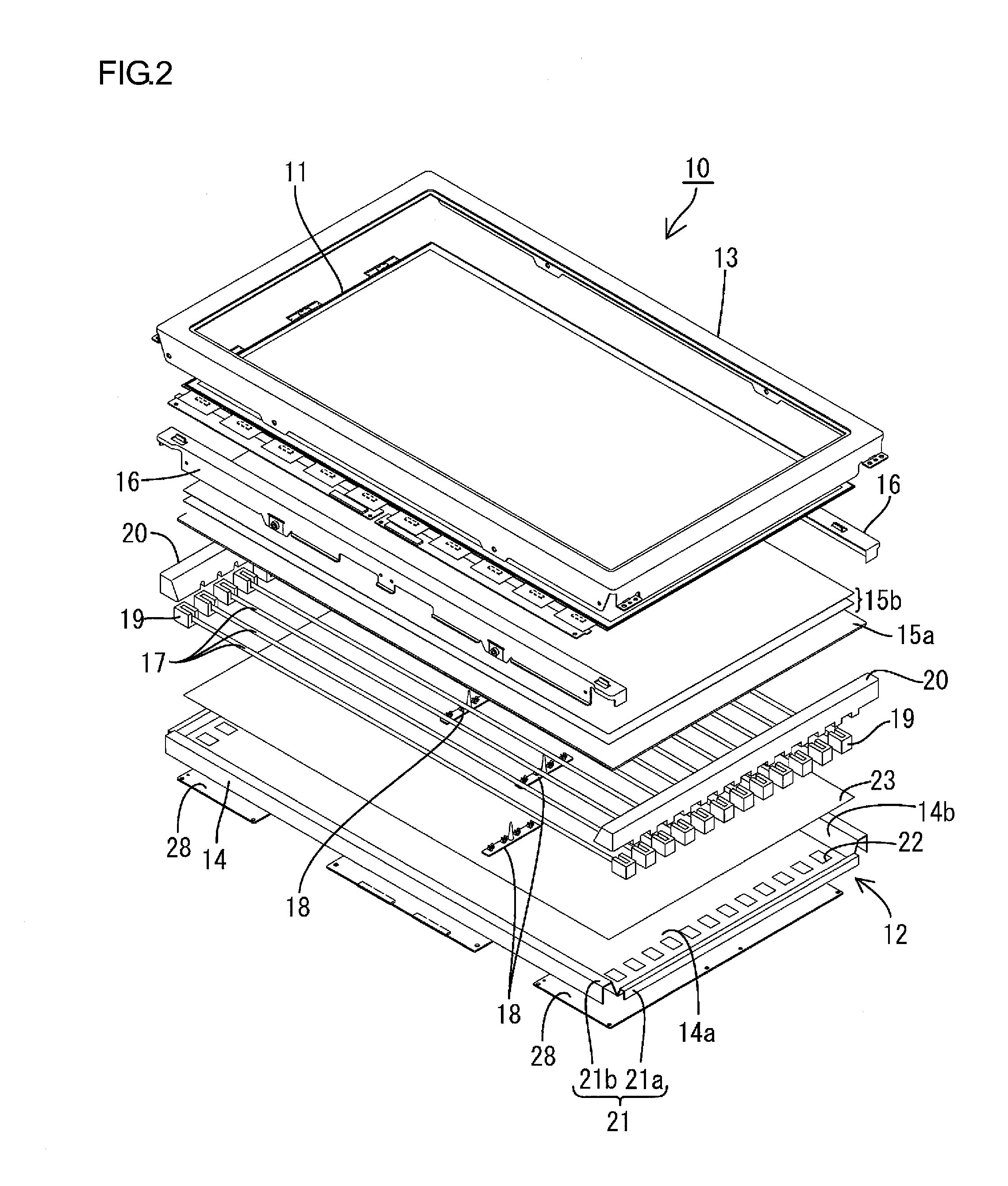
[0052]FIG. 1 is an exploded perspective view illustrating a general construction of the television receiver of this embodiment. FIG. 2 is an exploded perspective view illustrating a general construction of the liquid crystal display device included in the television receiver in FIG. 1. FIG. 3 is a cross-sectional view of the liquid crystal display device in FIG. 2 along the short-side direction. FIG. 4 is a cross-sectional view of the liquid crystal display device in FIG. 2 along the long-side direction. FIG. 5 is a plan view illustrating a general construction of cold cathode tubes and a chassis included in the liquid crystal display device in FIG. 2. In FIG. 5, the long-side direction of the chassis is referred to as an X-axis direction and the short-side direction...

second embodiment

[0112]A second embodiment of the present invention will be explained with reference to FIGS. 16 to 20. The second embodiment differs from the first embodiment in that an arrangement configuration of the cold cathode tubes is changed, and other components and configurations are same as the above embodiment. The same parts as the above embodiment are indicated by the same symbols and will not be explained. FIG. 16 is a cross-sectional view of the liquid crystal display device along the short-side direction according to the second embodiment. FIG. 17 is a plan view illustrating a general construction of cold cathode tubes and a chassis provided in the liquid crystal display device.

[0113]A plurality of cold cathode tubes 17 are arranged in a portion of the chassis 14 such that they are arranged parallel to each other with having a relatively small distance therebetween. More specifically, as illustrated in FIGS. 16 and 17, a bottom plate 50 of the chassis 14 (a portion facing a light gu...

first modification

of Second Embodiment

[0141]One modification of the configuration of the light reflecting portions on the second surface 60b of the light guide plate 60 will be explained with reference to FIGS. 21 to 23. FIG. 21 is a plan view illustrating an enlarged general construction of the second surface of the light guide plate facing the optical sheets according to another modification. FIG. 22 is a plan view illustrating light reflectance of the entire second surface of the light guide plate in FIG. 21. FIG. 23 is a graph illustrating a reflectivity change in the short-side direction of the light guide plate in FIG. 21. In FIG. 23, a horizontal axis shows the Y-axis direction (short-side direction) and the light reflectance is plotted on a graph from the end closer to the Y1 (Y1 end) to the middle portion in the Y-axis direction and from the middle portion to the end closer to the Y2 (Y2 end).

[0142]The light reflecting portions 31-C and the light scattering portions 32 having a dot pattern a...


PUM


Abstract

A lighting device 12 of the present invention includes a light source 17, a chassis 14 housing the light source 17 and having an opening 14b for light from the light source 17 to pass through, and an optical member 15a provided so as to face the light source 17 and cover the opening 14b. The optical member 15a is formed of a member having a substantially uniform light reflectance, and has a first surface 30a facing the light source 17 and a second surface 30b opposite from the first surface 30a. A light reflecting portion 31 is formed on a portion of the second surface 30b that overlaps the light source 17. The light reflecting portion 31 reflects light from the first surface 30a. A light scattering portion 32 is formed on a portion of the optical member 15a that does not overlap the light source 17. The light scattering portion 32 scatters the light.

Description

TECHNICAL FIELD[0001]The present invention relates to a lighting device, a display device and a television receiver.BACKGROUND ART[0002]A liquid crystal panel included in a liquid crystal display device does not emit light, and thus a backlight device is required as a separate lighting device. The backlight device is arranged behind the liquid crystal panel (i.e., on a side opposite from a display surface side). It includes a chassis having an opening on a liquid crystal panel side, a plurality of fluorescent tubes accommodated in the chassis as light sources, and a diffuser plate and the like provided at the opening of the chassis for efficiently directing light emitted from the fluorescent tubes to a liquid crystal panel.[0003]In such a backlight device where the fluorescent tubes emit linear light, a plurality of fluorescent tubes are aligned with each other and the optical member converts linear light into planer light to unify illumination light. However, if the linear light is...

Claims


Application Information

Patent Timeline
IPC IPC(8): G02F1/13357F21V7/00F21V13/10F21V29/00
CPCG02F1/133604G02F1/133611G02F1/133606
Inventor TAKATA, YOSHIKI
Owner SHARP KK
Why Eureka
Try Eureka