Multi-segment optical retarder for creating 3D images

Inactive Publication Date: 2011-02-10
VIAVI SOLUTIONS INC
View PDF37 Cites 141 Cited by
  • Summary
  • Abstract
  • Description
  • Claims
  • Application Information

AI Technical Summary

Benefits of technology

[0010]The instant invention relates to a multi-segment optical retarder that can be used with or within a single projector for creating 3D images. The multi-segment optical retarder is coupled to an actuator used to effect some predetermined linear, rotary, or oscillating movement of the multi-segment optical retarder such that a fast axis orientation of

Problems solved by technology

Unfortunately, these systems can be very expensive.
In addition, since the glasses must be accurately synchronized with the projector that sends the images to the display, it can be challenging to achieve the necessary synchronization between the glasses and the signal source.
Unfortunately, this technology has severe limitations, including poor color fidelity due to the use of tinted glasses.
Unfortunately, this projection system is also costly, as it typically requires two projectors.
While the cost of these s

Method used


Image

  • Multi-segment optical retarder for creating 3D images
  • Multi-segment optical retarder for creating 3D images
  • Multi-segment optical retarder for creating 3D images

Examples


Embodiment Construction

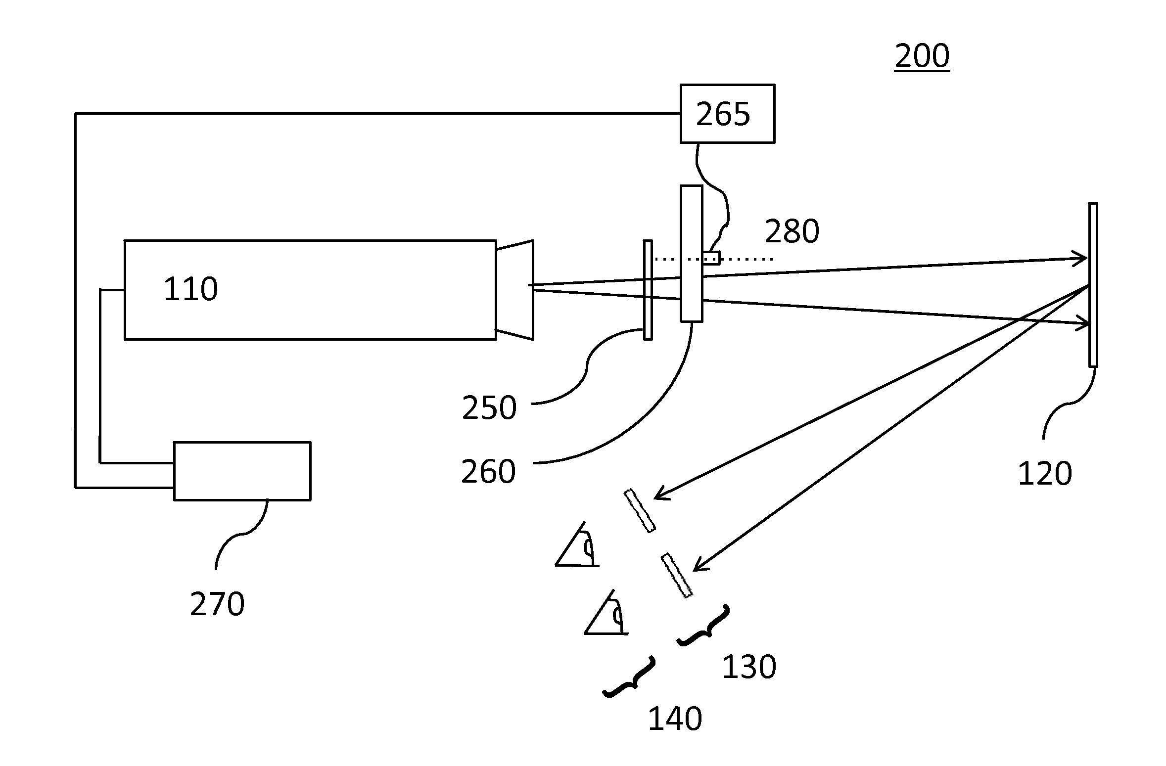
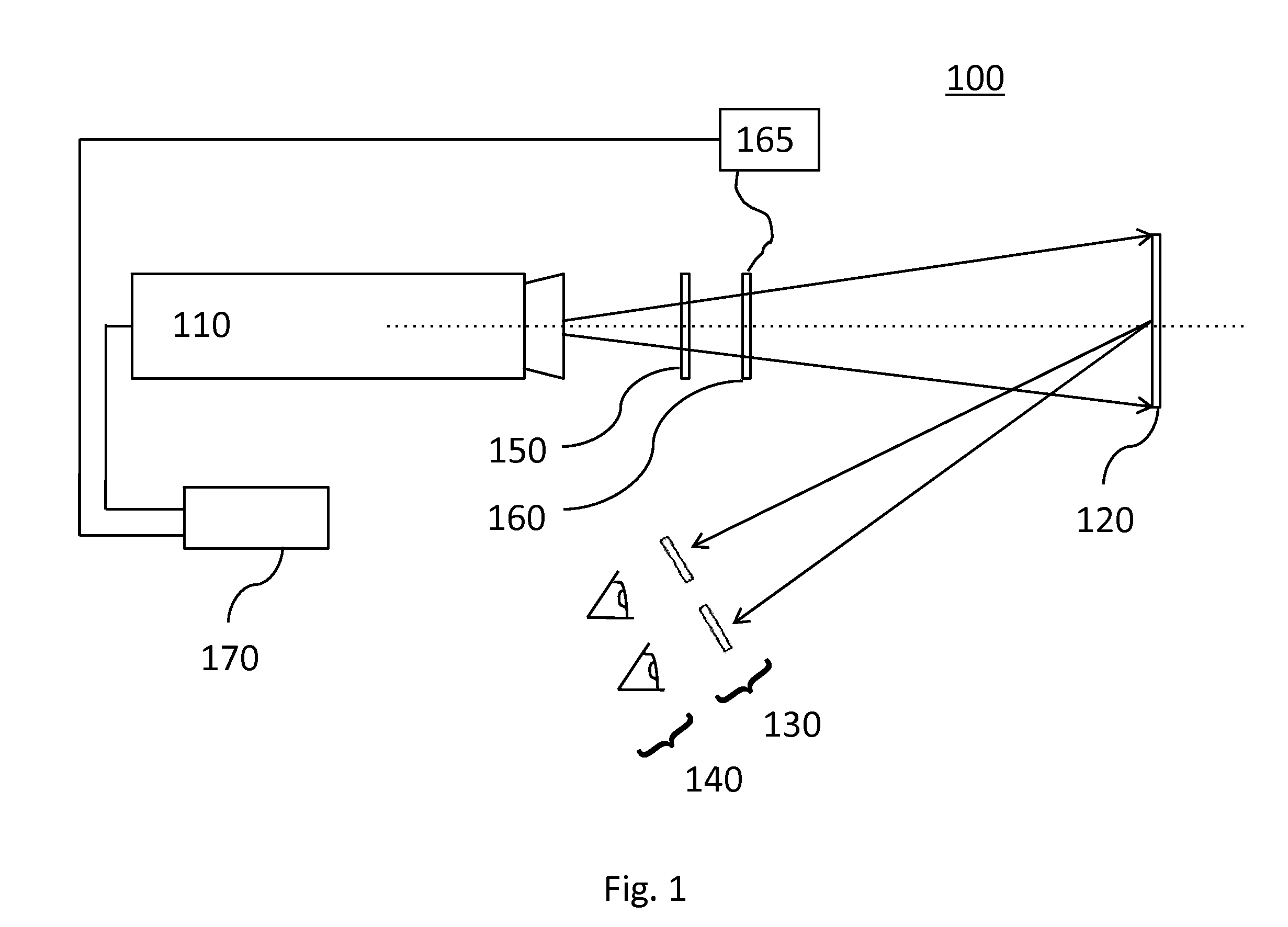
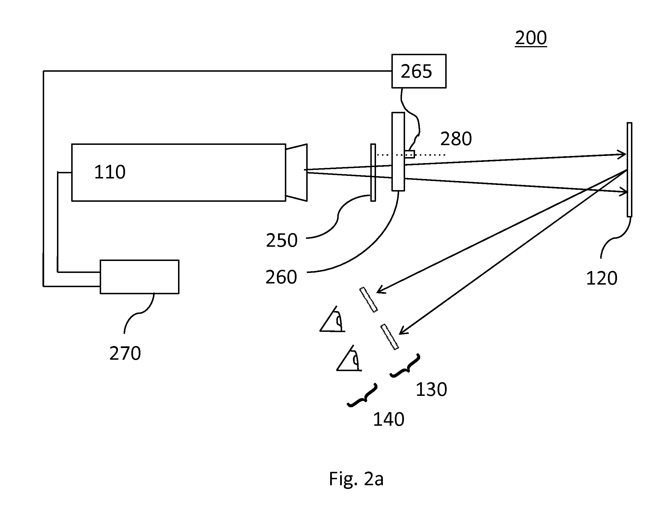
[0043]Referring to FIG. 1, there is shown a projection system in accordance with one embodiment of the instant invention. The projection system 100 includes an image projector 110, a projection screen 120, and eyewear 130, which is typically worn by a viewer 140. The projection system 100 also includes a stationary polarizer 150, a mechanically actuated optical retarder 160, and a controller 170.

[0044]The projector 110 is used to generate stereoscopic images that are projected onto the projection screen 120. For example, in one embodiment the stereoscopic images correspond to original movie content originated from two cinema cameras separated by a small angle. In another embodiment, the stereoscopic images correspond to still photography originated from two cameras providing different viewpoints. In yet another embodiment, the stereoscopic images are animated and / or computer generated. Various projector architectures are suitable for use in the projector 110. For example, suitable p...


PUM


Abstract

A multi-segment optical retarder that can be used with or within a single projector for creating 3D images. The multi-segment optical retarder is coupled to an actuator used to effect some predetermined linear, rotary, or oscillating movement of the multi-segment optical retarder such that a fast axis orientation of each segment is substantially constant relative to itself over time and for a given area of incidence.

Description

CROSS-REFERENCE TO RELATED APPLICATIONS[0001]This application claims priority from U.S. Provisional Application No. 61 / 232,150 filed Aug. 7, 2009, which is hereby incorporated by reference for all purposes.MICROFICHE APPENDIX[0002]Not Applicable.TECHNICAL FIELD[0003]The present application relates generally to multi-segment optical retarders, and in particular to multi-segment optical retarders for creating 3D images.BACKGROUND OF THE INVENTION[0004]Various techniques have been proposed to create realistic three-dimensional (3D) images, as perceived by a viewer. In general, most of these techniques involve using an image projector to project stereoscopic images onto a remote display screen. For example, original movie content originating from two cinema cameras separated by a small angle can be used to generate the stereo effect. When a viewer processes the images from each camera with a different eye, the viewer interprets these two related viewpoints as a 3D image of the correspon...

Claims


Application Information

Patent Timeline
IPC IPC(8): G02B27/26G03B21/14G02B27/28G02B30/25
CPCG02B26/008G02B27/286G02B27/26G03B35/26G02B30/25
Inventor HRUSKA, CURTIS R.SHEMO, DAVID M.TAN, KIM LEONG
Owner VIAVI SOLUTIONS INC
Why Eureka
Try Eureka