
Acoustic velocity microphone using a buoyant object

a technology of acoustic velocity and a microphone, which is applied in the direction of transducer details, electrical transducers, electrical apparatus, etc., can solve the problems of insufficient acoustic pressure sensing alone, sensor failure, and inability to distinguish the direction of an incident sound wav

Active Publication Date: 2011-02-10
DENG KEN K
View PDF17 Cites 24 Cited by
  • Summary
  • Abstract
  • Description
  • Claims
  • Application Information

AI Technical Summary

Benefits of technology

"The patent text describes an invention that addresses the need for a vector type acoustic sensor, such as an acoustic velocity microphone, that is not a scalar pressure microphone. The current approaches rely on the acoustic pressure gradient to create the sensor's output. The invention provides a method for creating a vector type acoustic sensor that uses a finite difference method to measure the pressure gradient and particle velocity of an acoustic wave. This allows for a more complete understanding of the sound behavior in various applications. The invention also includes different embodiments and arrangements of components to achieve the vector type acoustic sensor."

Problems solved by technology

Most microphones, i.e., sensors, can only measure acoustic pressure and cannot distinguish the direction of an incident sound wave.
In many applications, acoustic pressure sensing alone is not enough.

Method used


Image

  • Acoustic velocity microphone using a buoyant object
  • Acoustic velocity microphone using a buoyant object
  • Acoustic velocity microphone using a buoyant object

Examples


Embodiment Construction

[0020]There is a strong need for a vector type acoustic sensor such as an acoustic velocity microphone that is not a scalar pressure microphone. Currently two approaches exist for directional acoustic sensing. Fundamentally, both approaches rely on the acoustic pressure gradient to create the sensor's output.

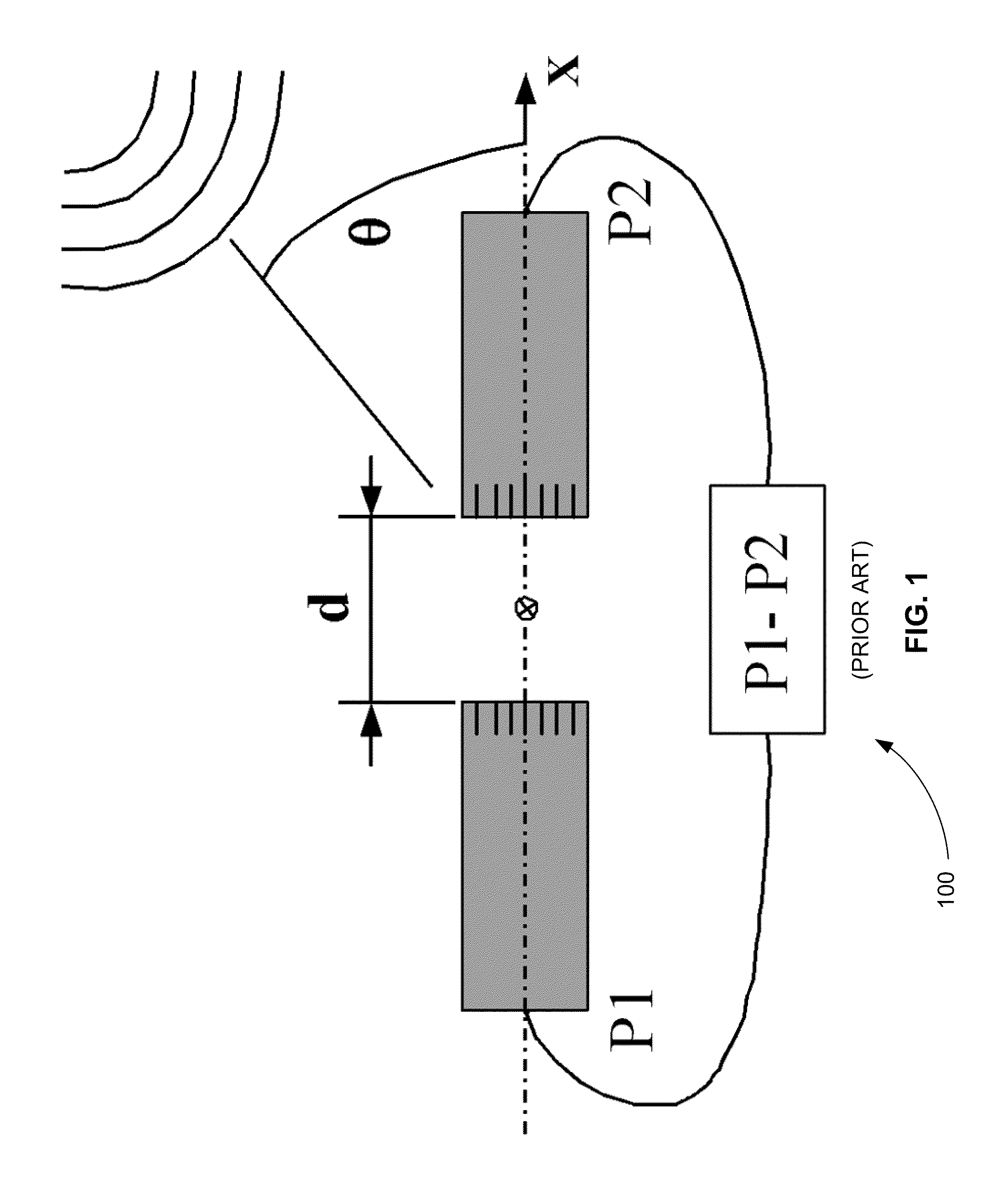
[0021]FIG. 1 is a schematic diagram of an exemplary prior art pressure gradient sensor 100 using a finite difference method. Pressure gradient sensor 100 includes two matched omnidirectional microphones separated by a small distance d. A plane acoustic wave of amplitude P incident at an angle θ relative to the line along spacing d (designated as X axis in graph) can be expressed as,

p(x,t)=P·ej(ωt−kx·cos θ)  (1)

where k is wave number (k=ω / c) and c is sound speed in air, ω is angular frequency.

[0022]The derivative of this pressure function with respect to distance x is the pressure gradient along X axis.

∂p(x,t)∂x=jωc·P·cosθ·jωt(2)

[0023]The output of the sensing system in FIG. 1 is...


PUM


Abstract

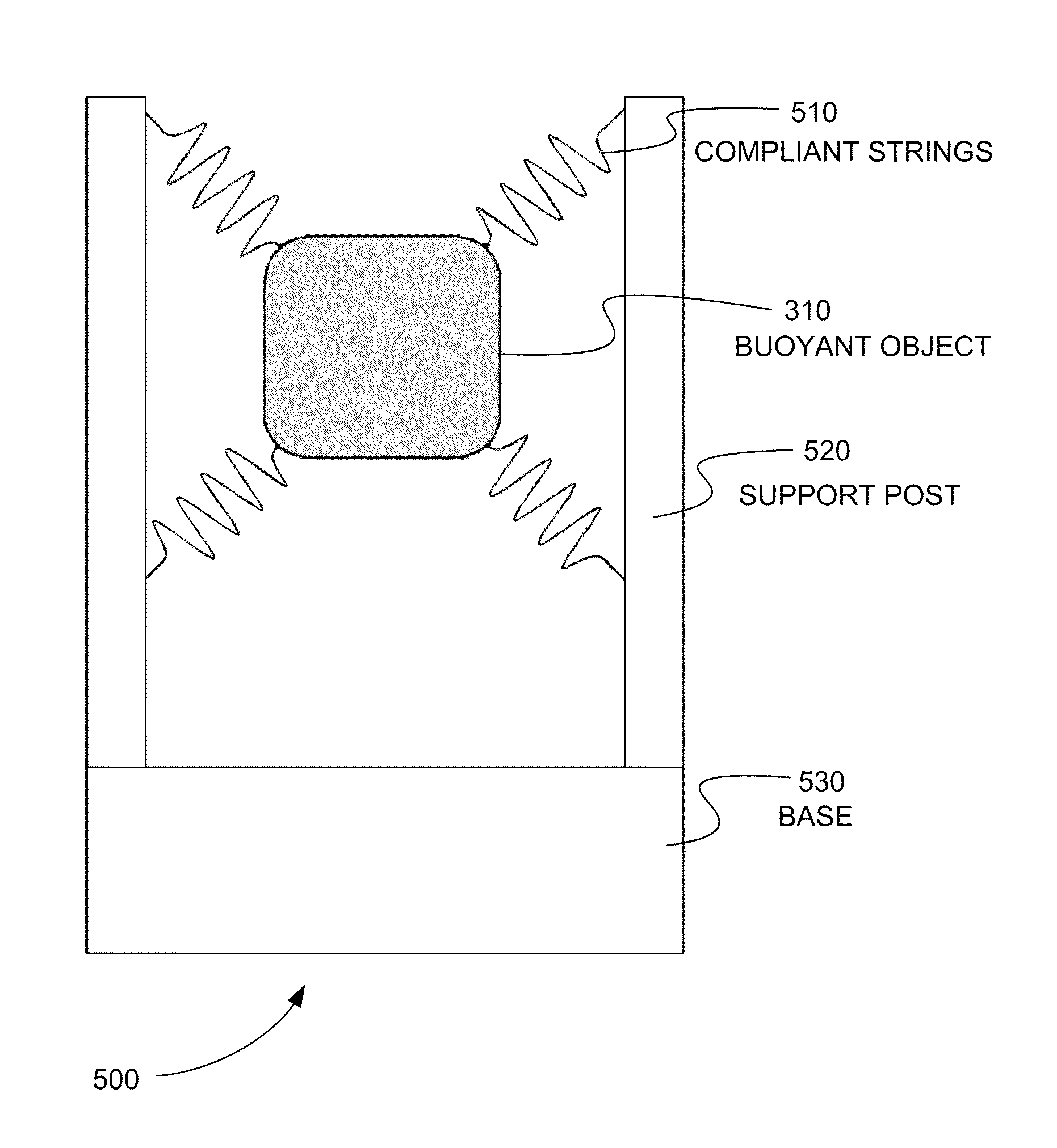
Embodiments of a directional acoustic sensor or acoustic velocity microphone are disclosed that include a sensor frame structure, a support means, and a buoyant object. The buoyant object is suspended in the sensor frame structure using the support means. The buoyant object has a feature size smaller than a wavelength of the highest frequency of an acoustic wave in air. The buoyant object receives three-dimensional movement of the air excited by the acoustic wave. The three-dimensional movement that the buoyant object receives is detected using a detection means. A particle velocity of the acoustic wave is derived from the three-dimensional movement of the buoyant object using the detection means. The detection means can be an optical detection means, an electromagnetic detection means, or an electrostatic detection means. An acoustic image of the acoustic wave can be determined by distributing two or more directional acoustic sensors a multi-dimensional array.

Description

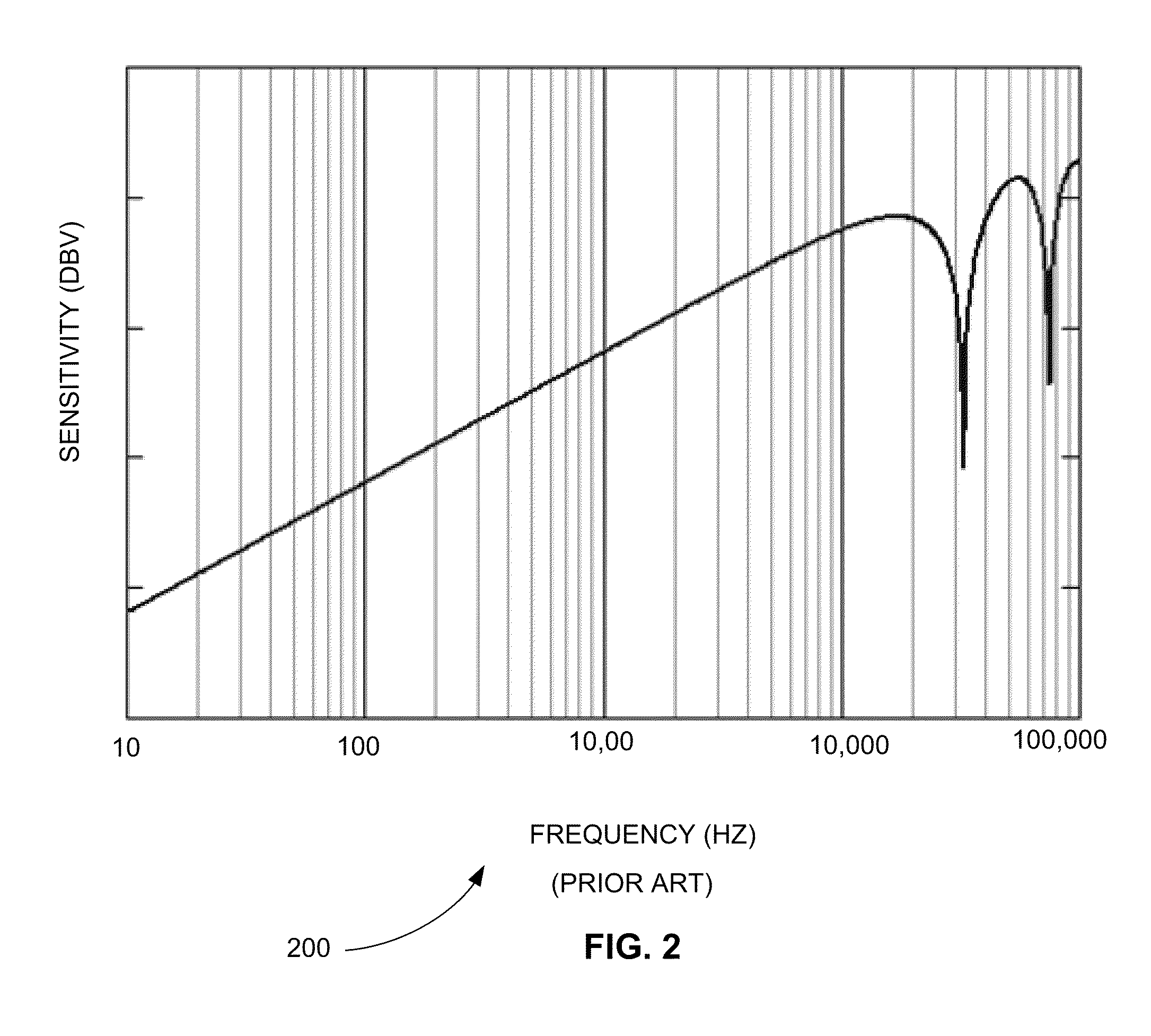
CROSS-REFERENCE TO RELATED APPLICATION[0001]This application claims the benefit of U.S. Provisional Patent Application No. 61 / 273,564, filed Aug. 6, 2009 and is hereby incorporated by reference in its entirety.INTRODUCTION[0002]Most microphones, i.e., sensors, can only measure acoustic pressure and cannot distinguish the direction of an incident sound wave. In other words, these microphones are omnidirectional sensors. A directional microphone / sensor is sensitive to the acoustic wave incident from one direction and insensitive to the waves from other directions. In many applications, acoustic pressure sensing alone is not enough. Other parameters, such as pressure gradient and particle velocity, are needed to fully understand the sound behavior in these applications.BRIEF DESCRIPTION OF THE DRAWINGS[0003]FIG. 1 is a schematic diagram of an exemplary prior art pressure gradient sensor using a finite difference method.[0004]FIG. 2 is an exemplary plot 200 of the frequency response of ...

Claims


Application Information

Patent Timeline
Patent Type & Authority Applications(United States)
IPC IPC(8): H04R3/00
CPCH04R1/38H04R3/005
Inventor DENG, KEN K.
Owner DENG KEN K
Learn More