Circulating System for a Linear Guideway

a technology of circulating system and linear guideway, which is applied in the direction of linear bearings, shafts and bearings, bearings, etc., can solve the problems of high cost and corresponding increase in machining accuracy, and achieve the effects of reducing noise, reducing machining costs, and facilitating quick mass production

Active Publication Date: 2011-02-10
HIWIN TECH
View PDF12 Cites 24 Cited by
  • Summary
  • Abstract
  • Description
  • Claims
  • Application Information

AI Technical Summary

Benefits of technology

[0015]The primary objective of the present invention is to provide a circulating system for a linear guideway which can reduce the machining cost and facilitate quick mass production by utilizing a common plastic injection molding method to make the cover plates and the end caps.
[0016]The secondary objective of the present invention is to provide a circulating system for a linear guideway which can reduce noise by combining cover plates and end caps to make the inner return blocks and the outer return blocks between the cover plates and the end caps form plural complete rolling paths which are made of plastic material and can avoid the noise caused by collision between metals when the rolling elements roll therein.
[0017]The third objective of the present invention is to provide a circulating system for a linear guideway which can reduce the machining cost of the slide block by making the rolling paths with plastic material to reduce the machining accuracy of the slide block.

Problems solved by technology

In the existing circulating systems for a linear guideway, the non-loaded rolling paths are mostly made of metal combined with plastic material which will produce a loud noise when in use, however, although the non-loaded rolling paths are made by insert injection molding to solve the problem of noise, the machining accuracy is correspondingly increased, thus suffering from the defect of high cost.

Method used


Image

  • Circulating System for a Linear Guideway
  • Circulating System for a Linear Guideway
  • Circulating System for a Linear Guideway

Examples


first embodiment

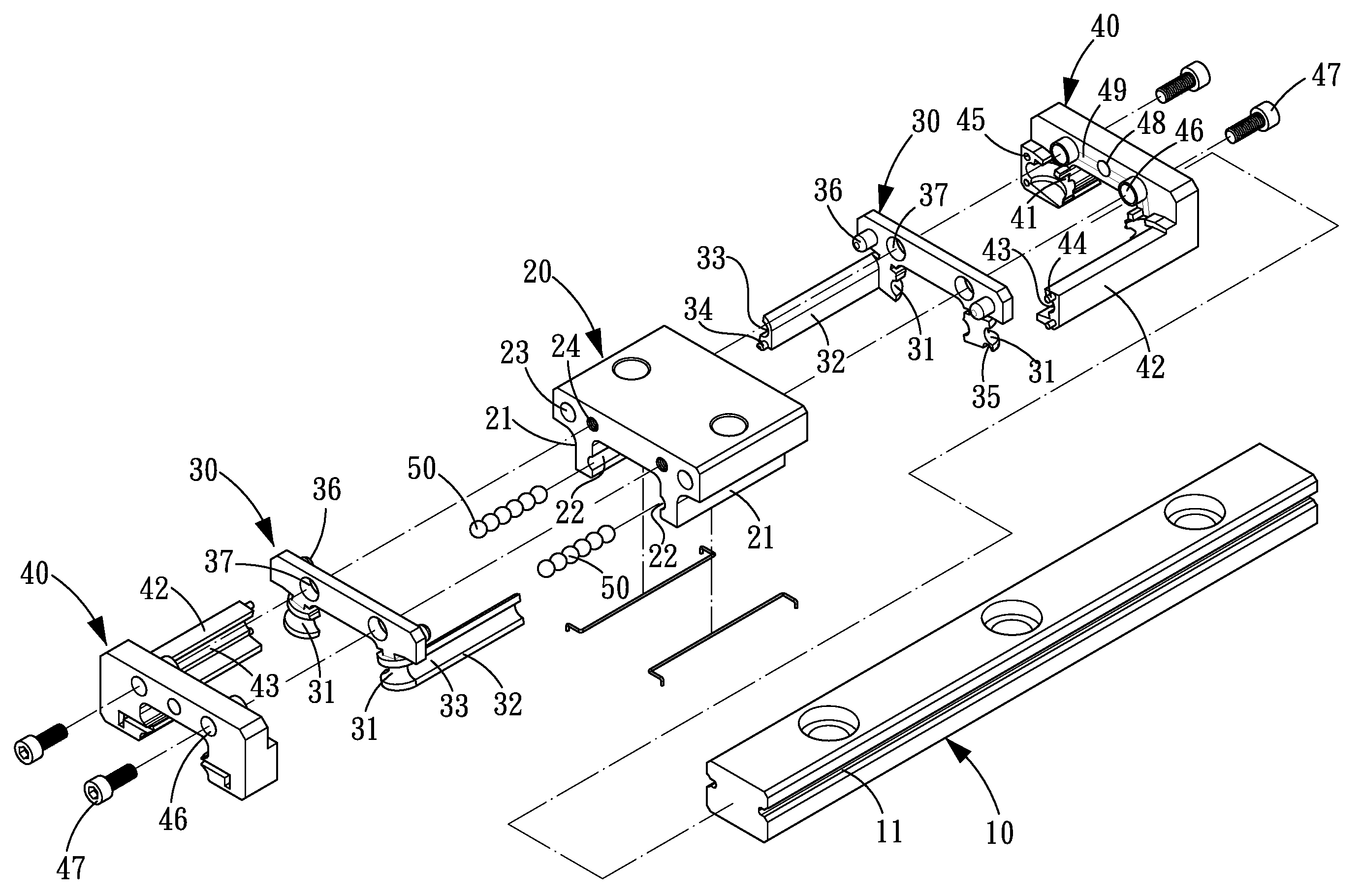
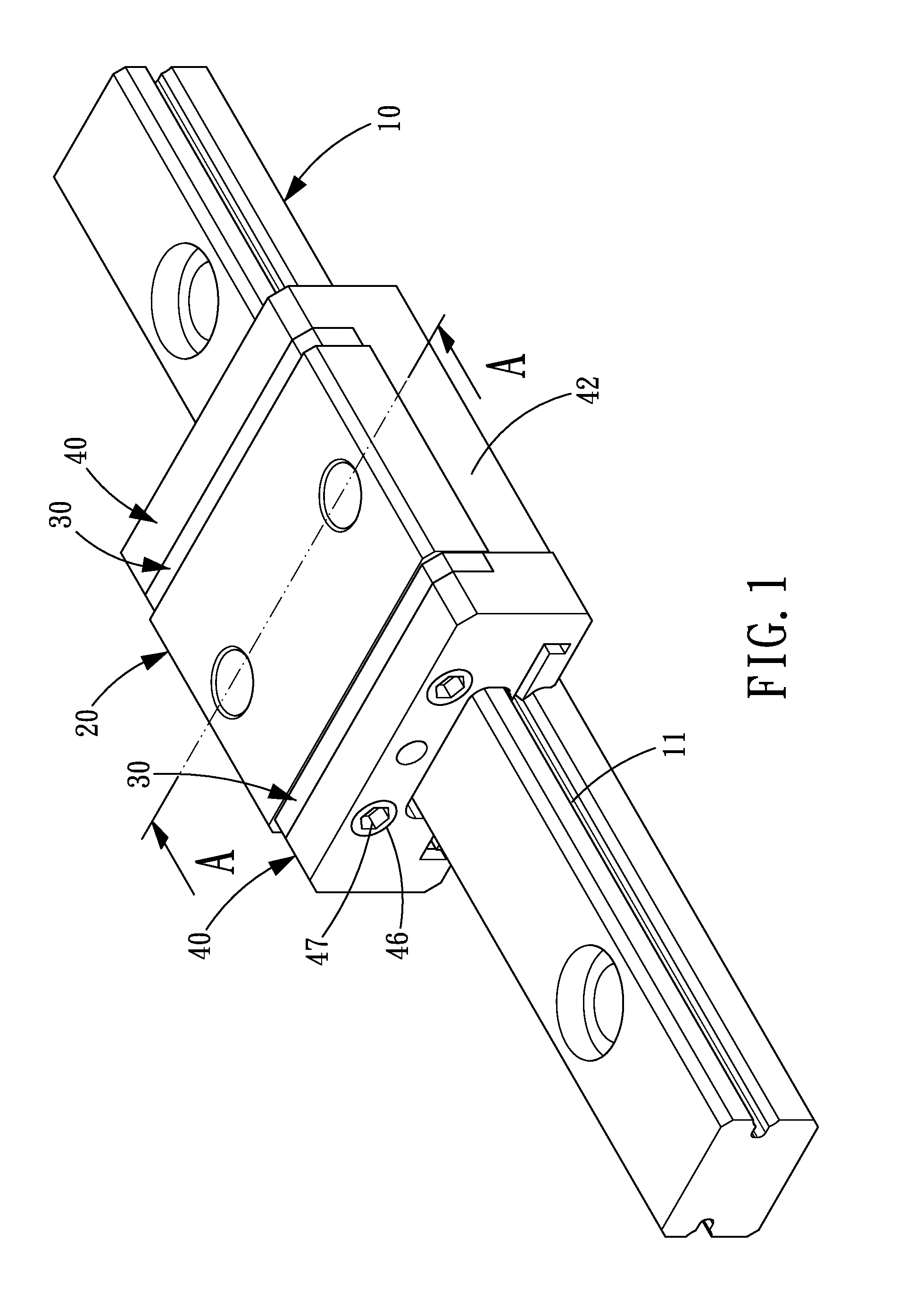
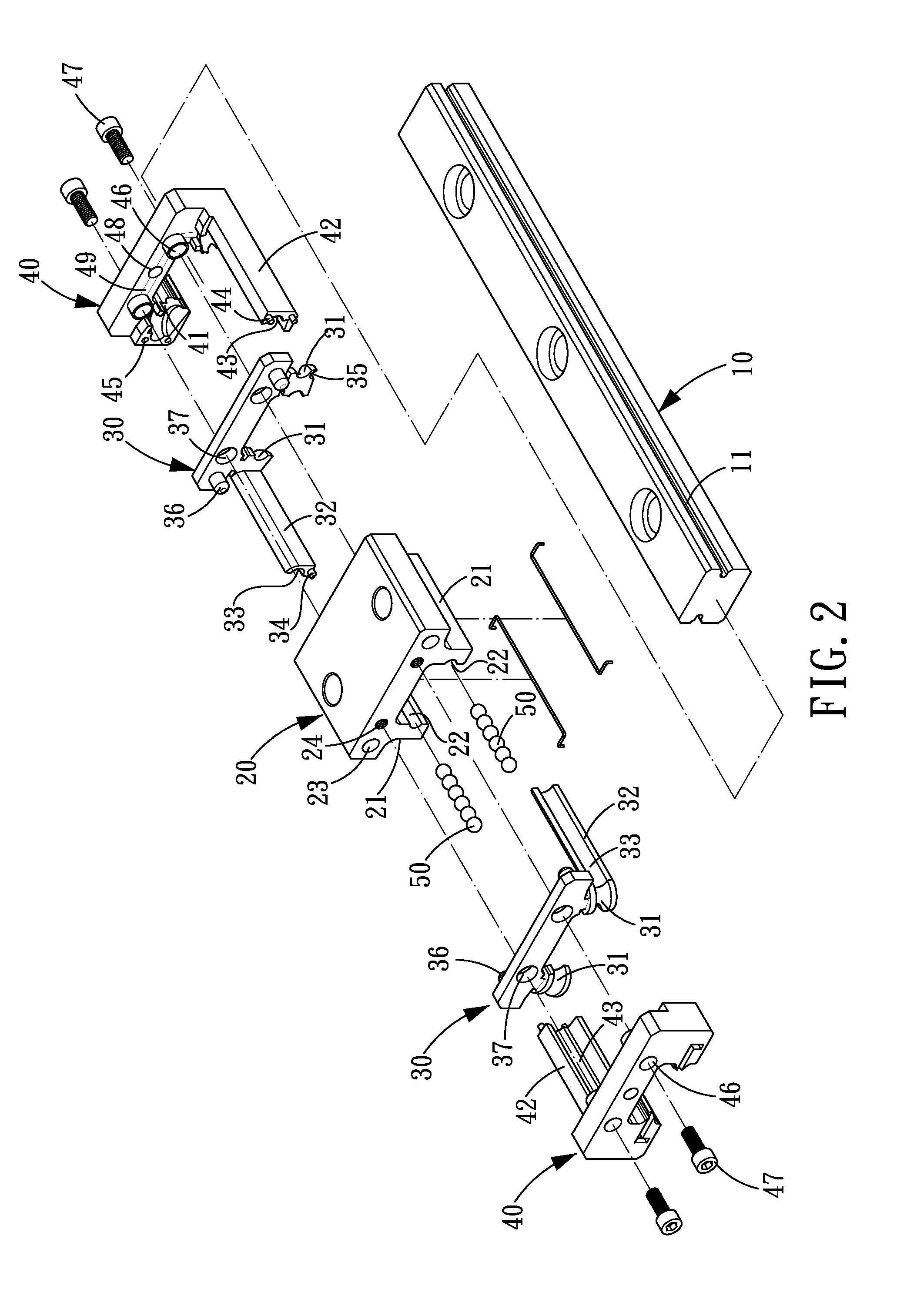
[0036]Referring to FIGS. 1-4, a circulating system for a linear guideway in accordance with the present invention comprises a slide rail 10, a slide block 20, two cover plates 30, two end caps 40 and plural rolling elements 50.

[0037]The slide rail 10 is made of metal and defined with a rail groove 11 at each of two opposite sides thereof.

[0038]The slide block 20 is made of metal. The slide block 20 is provided with an assembling portion 21 at each of two opposite outer sides of a bottom thereof. The slide block 20 is slidably mounted on the slide rail 10. The slide block 20 is further defined with a block groove 22 at each of two opposite sides thereof, and the two block grooves 22 cooperate with the two rail grooves 11 of the slide rail 10, respectively to form two complete loaded paths. The slide block 20 is defined with plural limiting holes 23 and plural locking holes 24 in each of two opposite ends thereof.

[0039]The two cover plates 30 are made of soft plastic material and disp...

second embodiment

[0043]Referring to FIGS. 6-8, a circulating system for a linear guideway in accordance with the present invention comprises a slide rail 10A, a slide block 20A, two cover plates 30A, two end caps 40A and plural rolling elements 50A.

[0044]The slide rail 10A is made of metal and defined with a rail groove 11A at each of two opposite sides thereof.

[0045]The slide block 20A is made of metal. The slide block 20A is provided with an assembling portion 21A at each of two opposite outer sides of a bottom thereof. The slide block 20A is slidably mounted on the slide rail 10A. The slide block 20A is further defined with a block groove 22A at each of two opposite sides thereof, and the two block grooves 22A cooperate with the two rail grooves 11A of the slide rail 10A, respectively to form two complete loaded paths. The slide block 20A is defined with plural limiting holes 23A and plural locking holes 24A in each of two opposite ends thereof.

[0046]The two cover plates 30A are made of soft plas...

third embodiment

[0050]Referring to FIGS. 9-11, a circulating system for a linear guideway in accordance with the present invention comprises a slide rail 10B, a slide block 20B, two cover plates 30B, two inner return blocks 32B, two end caps 40B and plural rolling elements 50B.

[0051]The slide rail 10B is made of metal and defined with a rail groove 11B at each of two opposite sides thereof.

[0052]The slide block 20B is made of metal. The slide block 20B is provided with an assembling portion 21B at each of two opposite outer sides of a bottom thereof. The slide block 20B is slidably mounted on the slide rail 10B. The slide block 20B is further defined with a block groove 22B at each of two opposite sides thereof, and the two block grooves 22B cooperate with the two rail grooves 11B of the slide rail 10B, respectively to form two complete loaded paths. The slide block 20B is defined with plural limiting holes 23B and plural locking holes 24B in each of two opposite ends thereof.

[0053]The two cover pl...


PUM


Abstract

A circulating system for a linear guideway comprises a slide block, a slide rail, two cover plates, two end caps and plural rolling elements. The slide block is disposed on the slide rail. The two cover plates and the two end caps are disposed at two opposite ends of the slide block, respectively. Between the two cover plates and the two end caps are disposed inner return and outer return blocks, respectively, and the inner return and the outer return blocks each are defined with half rolling paths to form complete rolling paths. Both ends of a complete rolling path and both ends of a complete loaded path are connected to both ends of two complete return paths to complete circulation paths. The inner and outer return blocks are made by common plastic injection molding, and the formed rolling paths are made of plastic material.

Description

BACKGROUND OF THE INVENTION[0001]1. Field of the Invention[0002]The present invention relates to a circulating system for a linear guideway; and more particularly to a circulating system for a linear guideway in which cover plates and end caps are improved.[0003]2. Description of the Prior Art[0004]Conventionally, in order to reduce friction coefficient of the slide block and noise caused by movement of the slide block, between the slide block and the slide rail is normally provided a circulating system for balls to roll therein. The circulating system includes two end caps at both ends of the slide block, plural loaded paths between the slide block and the slide rail, and plural non-loaded paths passing through the slide block. Furthermore, the respective end caps are defined with a return path for connecting the loaded paths to the respective non-loaded paths to form a complete circulation path. Since the slide block and the rail are load-carrying structures, they are both made of...

Claims


Application Information

Patent Timeline
Patent Type & Authority Applications(United States)
IPC IPC(8): F16C29/06
CPCF16C29/0609F16C29/0664F16C29/0657F16C29/0611
Inventor CHEN, TSUNG-JENYU, CHE-HSUANLIU, HSIN-PING
Owner HIWIN TECH
Why Eureka
Try Eureka