Arrangement for neutralisation or microorganisms

Active Publication Date: 2011-02-10
ARC AROMA PURE
View PDF9 Cites 4 Cited by
  • Summary
  • Abstract
  • Description
  • Claims
  • Application Information

AI Technical Summary

Benefits of technology

[0009]One purpose of the present invention is to eliminate or at least mitigate the above disadvantages and to provide an improved arrangement and an improved method for the neutralization of microorganisms in a pumpable medium by exposing the medium to an electric field.

Problems solved by technology

When the food is heated during pasteurization, however, its taste and chemical composition may change due to the increase in temperature.
Another disadvantage with pasteurization is that a large amount of energy is needed to heat the food, and then cooling it to a suitable storage temperature.
Energy consumption is currently related to high costs that ultimately results in an increase in the cost of the processed food.
These methods are however, costly and often require the use of additional methods to achieve the desired end-result.
In this case, however, it is difficult to control the extent of the treatment, this since the electric field the field strength is difficult to predict.
Furthermore, the liquid flow velocity will differ at different location over the intersection of the tube, leading to an uneven treatment.
When the above method and arrangement is used a significant risk that the previously treated pumpable substance is contaminated in case something fails.
This risk exists because no measurement is performed where the actual electric field is ensured during the exposure.
Would therefore not properly treated pumpable substance be carried forward after treatment, then the previously treated substance is contaminated.
Furthermore, there are no organs to ensure that no air or gas bubbles are present in the substance being treated or that the substance can be pressurized to minimize the risk of air-filled cavities in the treated substance.

Method used


Image

  • Arrangement for neutralisation or microorganisms
  • Arrangement for neutralisation or microorganisms
  • Arrangement for neutralisation or microorganisms

Examples


Embodiment Construction

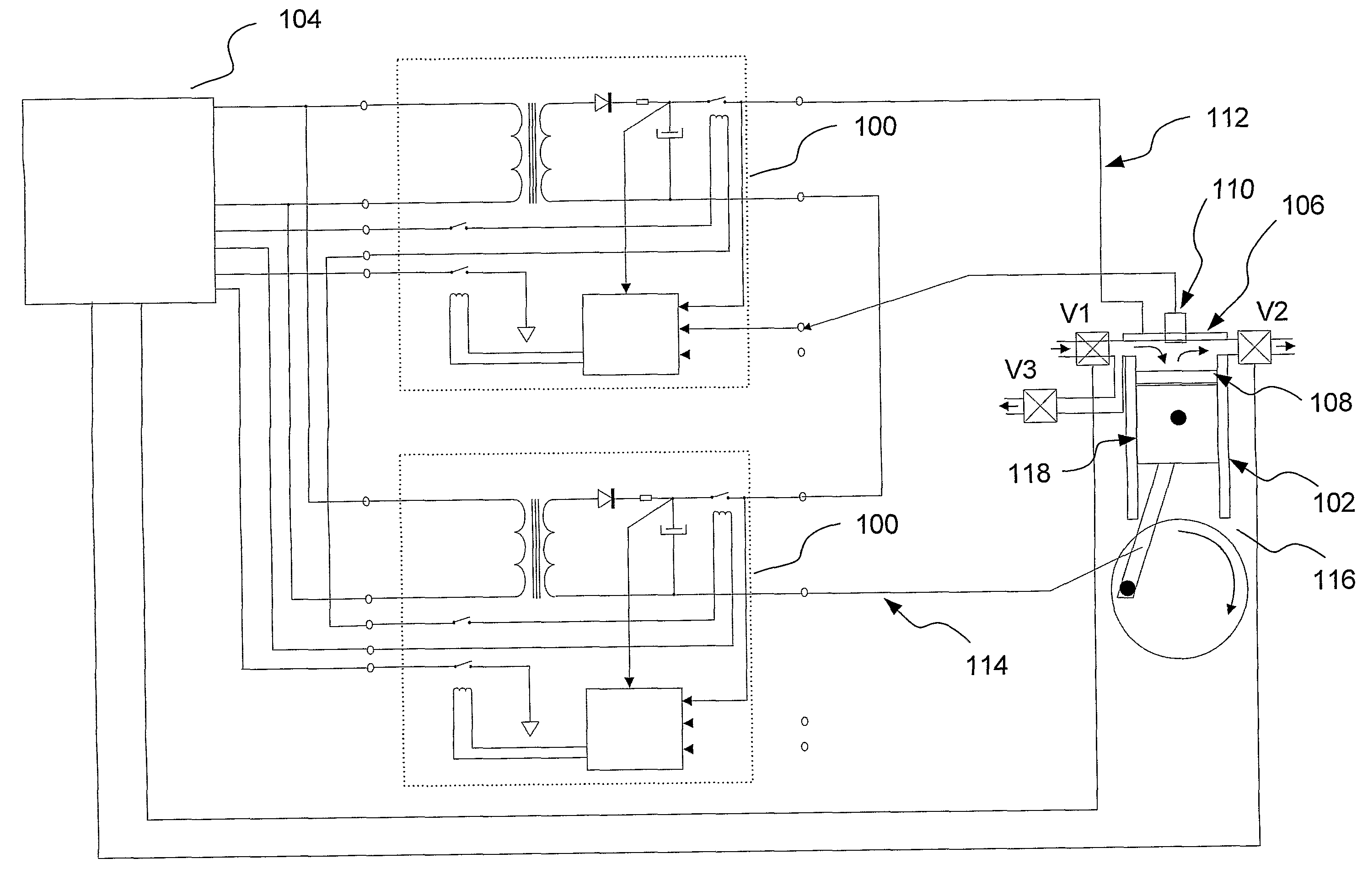
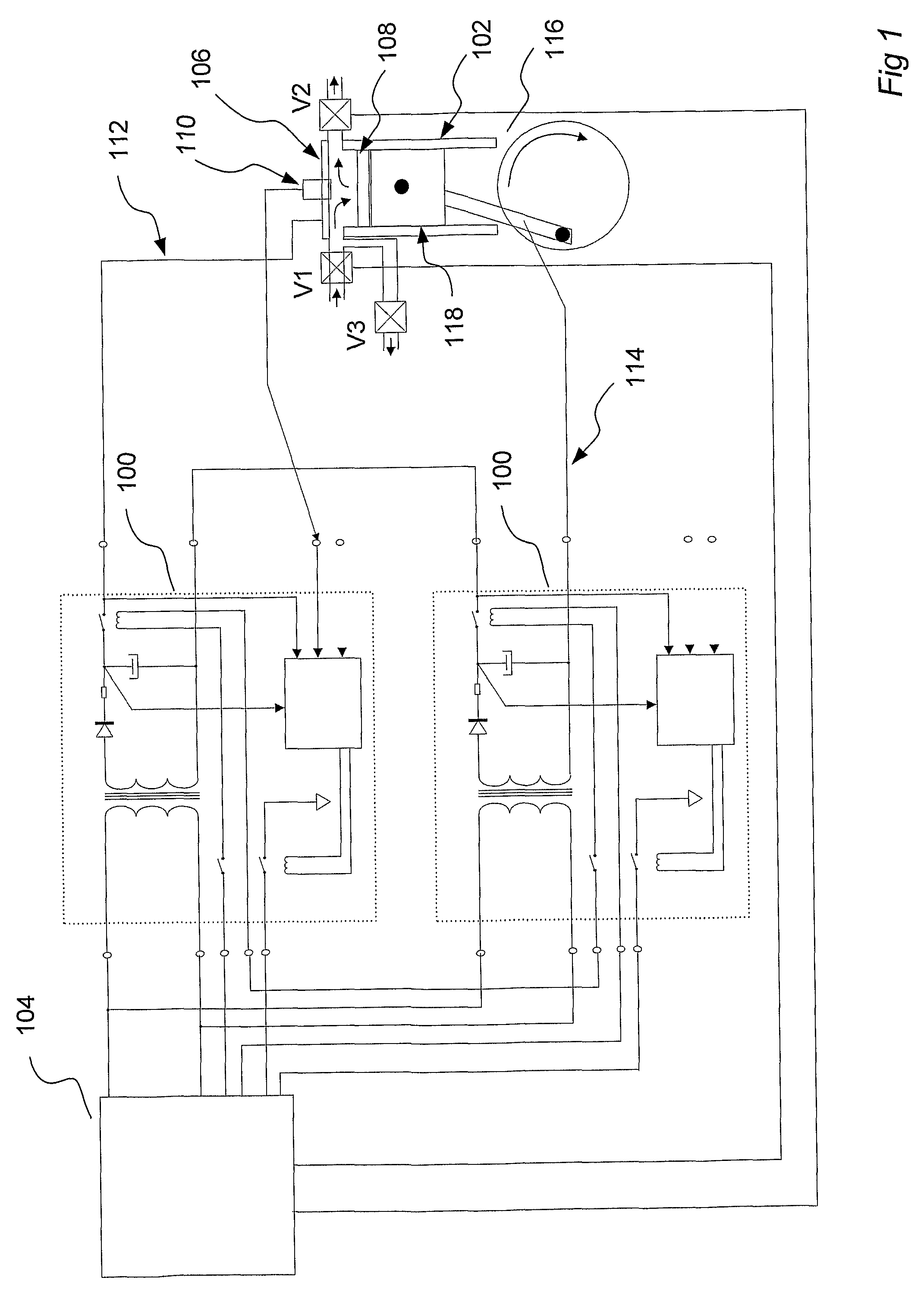
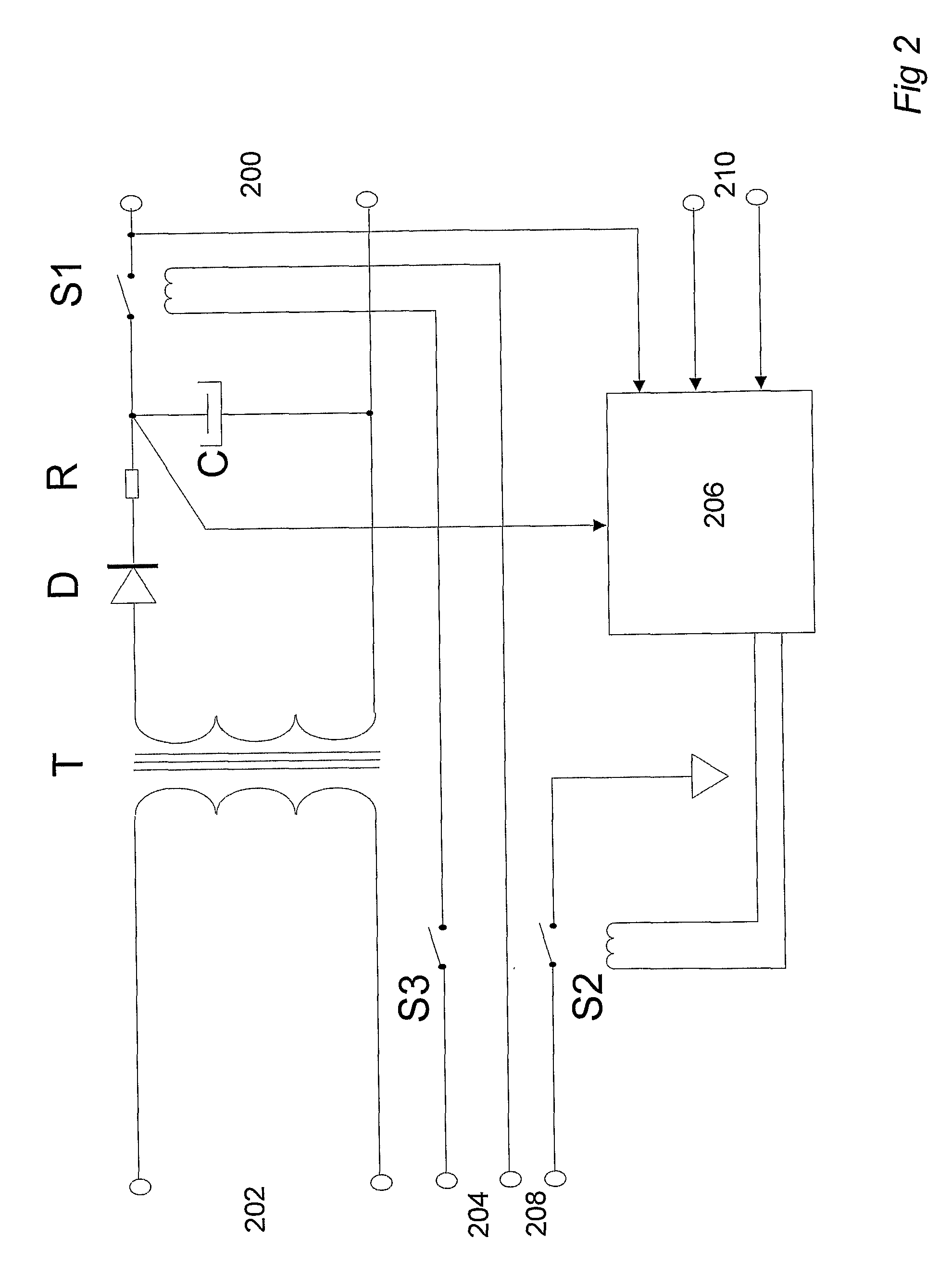
[0068]The arrangement in FIG. 1 includes two power supplies 100, which are shown in more detail in FIG. 2. Furthermore, the arrangement includes a non-conductive chamber 102 and a control means 104. The chamber 102 is equipped with a first electrode plate 106 and a second electrode plate 108. When the control means 104 establishes a serial connection between the two power supplies 100 a resulting composite voltage is produced between the first 106 and the second electrode plate 108. The resulting composite voltage will, when it is produced between the first 106 and the second electrode plate 108 generate an electrical field between electrode plates 106, 108. The resulting composite voltage is feed from the power supplies 100 to the first 106 and the second electrode plate 108 by means of electrical conductors 112, 114.

[0069]Since the purpose of the arrangement is to enable the exposure of the pumpable medium to an electric field to neutralize microorganisms, it is important that the...


PUM


Abstract

An arrangement for the exposure of a pumpable medium to an electric field. The arrangement comprises, at least two power supplies (100) for the generation of electrical voltage, at least one non-conducting chamber (102) for pumping said pumpable medium, which said at least one chamber (102) is provided with a first (106) and a second electrode plate (108), a control means (104) for controlling said at least two power supplies (100). During control the control means (104), by synchronous control, establishes a series connection between at least two of said at least two power supplies (100), the first electrode plate (106) and the second electrode plate (108). A resulting composite voltage arises between the first (106) and the second electrode plate (108), which resulting composite voltage will result in an electric field between the first (106) and the second electrode plate (108). The pumpable medium is exposed to the electric field. A method for the exposure of a pumpable medium to an electric field is also provided.

Description

TECHNICAL FIELD[0001]The present invention relates to an arrangement for the exposure of a pumpable medium to an electric field. The invention also concerns a method as performed expose a pumpable medium for an electric field. The invention relates also to a number of applications of the said arrangement.TECHNICAL BACKGROUND[0002]To destroy or inactivate harmful microorganisms in different types of fluids are today common in most application areas. For example, most liquid foodstuffs are exposed to one or more process steps that are designed to destroy unwanted microorganisms and thus extend the shelf life of the product. Similarly, different processes are used for purifying different kinds of contaminated water alternatively sludge, petroleum products or other pumpable products.[0003]A common method for food treatment is so-called pasteurization. During pasteurization the food in question is heated for a short period of time to a temperature which is high enough to inactivate the m...

Claims


Application Information

Patent Timeline
IPC IPC(8): A61L2/03B01J19/08A23L3/32C02F1/48
CPCA23L3/32A61L2/0011A61L2/03A61L2/24C02F2303/04C02F1/34C02F1/48C02F1/78C02F2201/008C02F1/32Y02W10/37Y10T137/218Y10T137/2185C02F1/008C02F2103/007C02F2103/008C02F2103/42A61K41/10
Inventor HENRIKSSON, PAR H.
Owner ARC AROMA PURE
Why Eureka
Try Eureka